
Tapered Spiral Welded Structure

a technology of welded structure and tapered spiral, which is applied in the direction of manufacturing tools, metal working apparatus, transportation and packaging, etc., can solve the problems of inability to produce the required conical structure without, the existing spiral welding technology is incapable of producing the required conical structure, and the process is impractical to achieve on site, so as to achieve the effect of large structur

Active Publication Date: 2011-07-28
KEYSTONE TOWER SYST
View PDF18 Cites 38 Cited by
  • Summary
  • Abstract
  • Description
  • Claims
  • Application Information

AI Technical Summary

Benefits of technology

Other and further objects will be explained hereinafter and more particularly delineated in the appended claims.
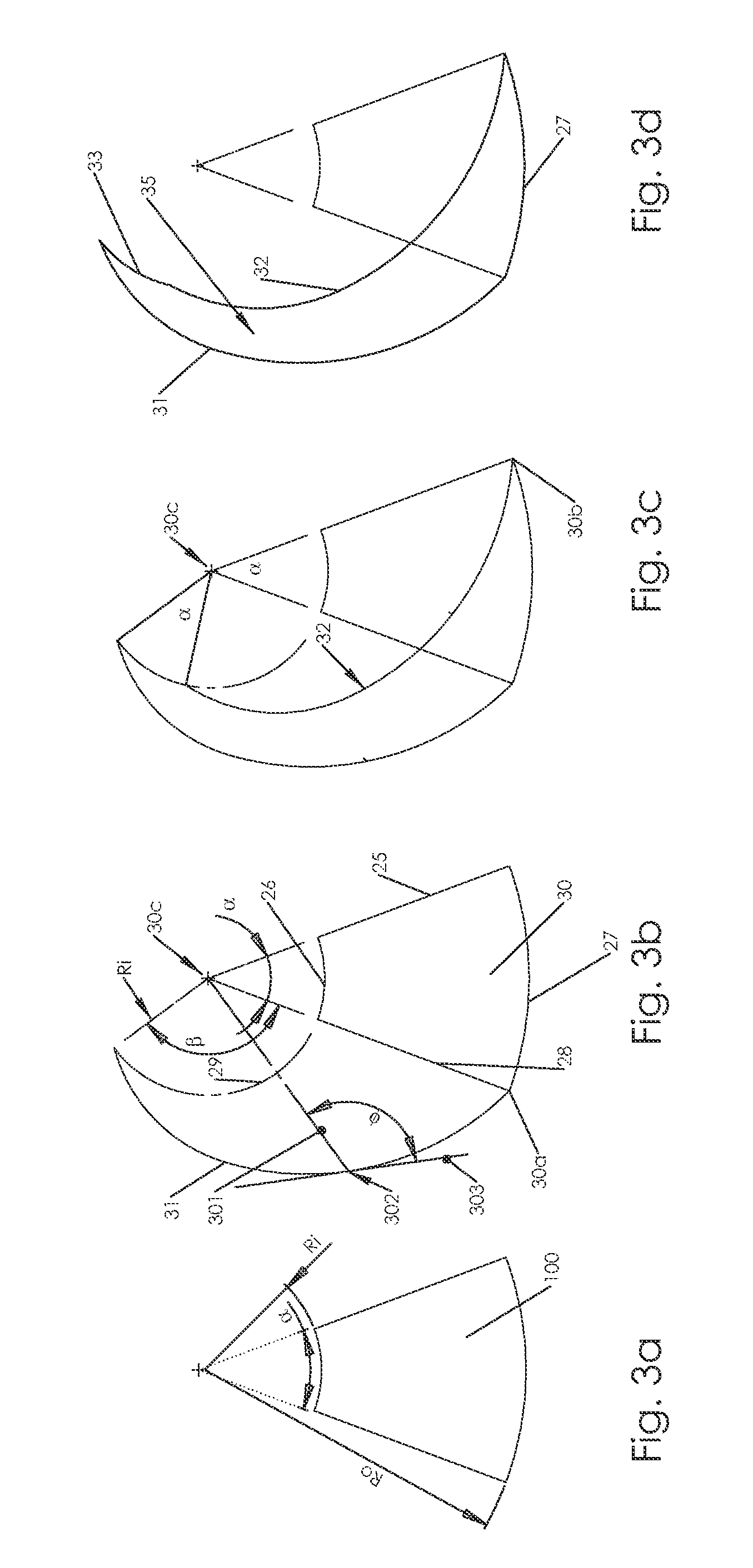
A method is presented for forming a tapered spiral welded conical structure where the overall shape of the cone is first graphically slit axially and unwrapped, and then a series of construction arcs and lines are created to form the edge lines of a strip that can then be wrapped (rolled) to form a tapered conical structure. The edges can be spiral welded together, and a very large structure can be achieved. Various construction options are presented from a constant width strip to strip made from straight segments. As and example, a constant width strip used to form a typical tower (2 m wide strip, 5.5 m to 2.5 m diameter cone, 100 m high) would have an in-plane radius of curvature that varies from around 180 m down to 80 m. Equations are given for the formation of the strips to enable those skilled in the art of spiral welded tubing to practice the invention.

Problems solved by technology

It could result in lighter weight for the same or greater height, compared to traditional towers that are transported to site and bolted together.
Existing spiral welding technology is incapable of producing the required conical structure without significant deformation of the metal stock, a process that is impractical to achieve on site.
U.S. Pat. No. 2,038,576 describes forming a cone from a piece of paper cut into an arc segment; however, the method does not allow for multiple wraps as would be required to form a large diameter cone from a single narrow strip of material; nor does the method have any logical extension to evolve into such a required shape as the radial edges of the paper force an axial seam and thus are inherently limiting on the length of the cone that can be formed to be less than the radial length of the edges.
While suitable for forming a shaft such as golf club, it would not be possible to provide a mandrel for a very large structure, such as a wind turbine tower.
While a mandrel is not required for this case, the order of size of the machine required to form the strip in this manner would make it difficult to realize for very large cones such as that required for large structures such as a windmill tower.
This will create the in-plane curvature required, but it is not applicable to the large 2 m wide strips needed for large structures, as the rolling forces in the cold state would be titanic and it would not be practical to heat the strip.
Furthermore, the described feedback system is only capable of finding the required curvature of the strip during the cone forming process.
However, this could decrease the buckling strength of the tower.
However, this results in great complexity and an enormous number of bolts to be installed and then periodically checked.

Method used


Image

  • Tapered Spiral Welded Structure
  • Tapered Spiral Welded Structure
  • Tapered Spiral Welded Structure

Examples


Embodiment Construction

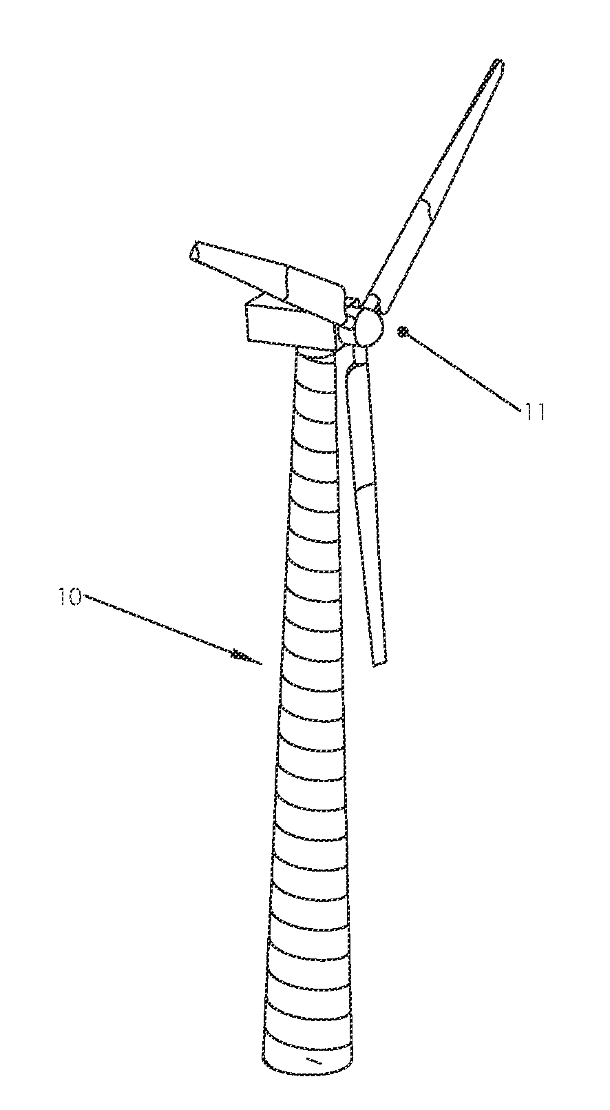
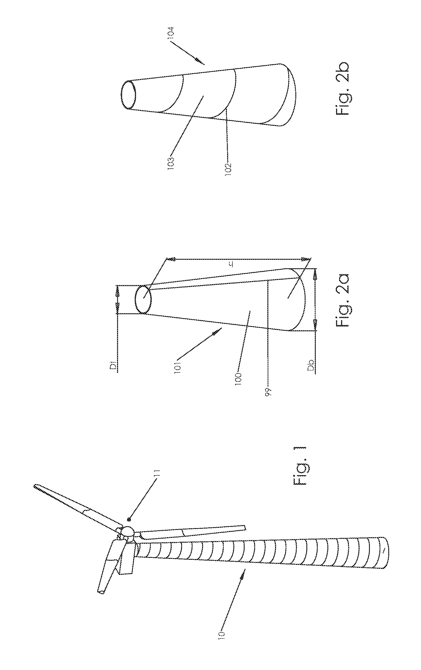
FIG. 1 shows a wind turbine 11 atop a tapered tower 10. Such towers are typically manufactured in segments from axially welded steel plate that are transported to site and assembled. This necessitates large bolted flange connections every 20 meters or so and the largest diameter that can be transported is typically 4-4.3 meters. By forming the sections on-site, diameters of 5 meters or more could be formed. Since the bending strength goes with the cube of the diameter, even a 10% increase in diameter represents a 33% increase in strength for only a 10% increase in weight if the same wall thickness structure is used. Going from a 4 meter diameter structure to a 5 meter diameter structure increases the strength by almost 100%. Hence there is a clear need to be able to make large conical towers on site so they can be used to support machines such as wind turbines shown in FIG. 1.

As discussed above, however, there has not been a simple and effective way to accomplish manufacturing of a ...


PUM

PropertyMeasurementUnit
diameteraaaaaaaaaa
diameteraaaaaaaaaa
diameteraaaaaaaaaa

Abstract

A method for creating a tapered spiral welded conical structure where the overall shape of the cone is first graphically slit axially and unwrapped, and then a series of construction arcs and lines are created to form the edge lines of a strip that can then be wrapped (rolled) to form a tapered conical structure. The edges of the spirally wound strip can be welded together, and a very large conical structure can thus be achieved. Various construction options are presented from a constant width strip to strip made from straight segments. Equations are given for the formation of the strips to enable those skilled in the art of spiral welded tubing to practice the invention.

Description

This invention relates to a method for creating tapered spiral welded structures from strips of material that either have been precut or formed and then are rolled and welded to form a tapered spiral welded structure, or a straight strip of material is notched and welded transversely in addition to being spirally welded. Such tapered towers can be manufactured on-site to enable very large diameter structural towers, not capable of being trucked to site.STATEMENT REGARDING FEDERALLY FUNDED RESEARCHNo federal funds were used in the development of this invention.FIELD OF THE INVENTIONThe present application relates to a method for defining the shape of a strip of metal that can then be formed into a spirally welded tapered conical structure.BACKGROUND OF THE INVENTIONA spiral welded conical structure that could be made on the construction site could be far more efficient than current designs of support structures such as wind turbine towers. It could result in lighter weight for the sa...

Claims


Application Information

Patent Timeline
Patent Type & Authority Applications(United States)
IPC IPC(8): B23P11/00
CPCY02E10/728B21C37/185Y10T29/49318Y10T29/49826Y10T428/12B21C37/124E04H12/08B23K31/02E04H12/342
Inventor SMITH, ERICSLOCUM, ALEXANDER
Owner KEYSTONE TOWER SYST
Learn More