Respirator or anesthesia apparatus

a technology of anesthesia apparatus and a respirator, which is applied in the direction of respirators, inhalators, etc., can solve the problems of large assembly effort, large length of flexible tubes with a correspondingly high pneumatic resistance, and the need for dead space, so as to achieve small space requirement and simple and reliable manner

Inactive Publication Date: 2011-07-14
DRAGERWERK AG
View PDF18 Cites 5 Cited by
  • Summary
  • Abstract
  • Description
  • Claims
  • Application Information

AI Technical Summary

Benefits of technology

The object of the present invention is therefore to make available a respirator or anesthesia apparatus, in which the modules of the respirator or anesthesia apparatus can be pneumatically connected to one another in a simple and reliable manner and the space requirement is small.

Problems solved by technology

The large number of necessary connections in a respirator or anesthesia apparatus and hence of flexible tubes and / or tube connections leads to a great assembly effort for connecting the modules to one another.
After the modules have been connected to the flexible tubes and / or tube connections, a complicated test is to be carried out in order to identify leaks or flexible tube connections plugged incorrectly into one another, because this represents a considerable potential hazard to the patients.
In case of short distances between two modules, this is only possible, in general with a large loop, which causes a great length of the flexible tube with a correspondingly high pneumatic resistance and dead space to be necessary.
A flexible tube is disadvantageously necessary herewith.

Method used


Image

  • Respirator or anesthesia apparatus
  • Respirator or anesthesia apparatus
  • Respirator or anesthesia apparatus

Examples


second exemplary embodiment

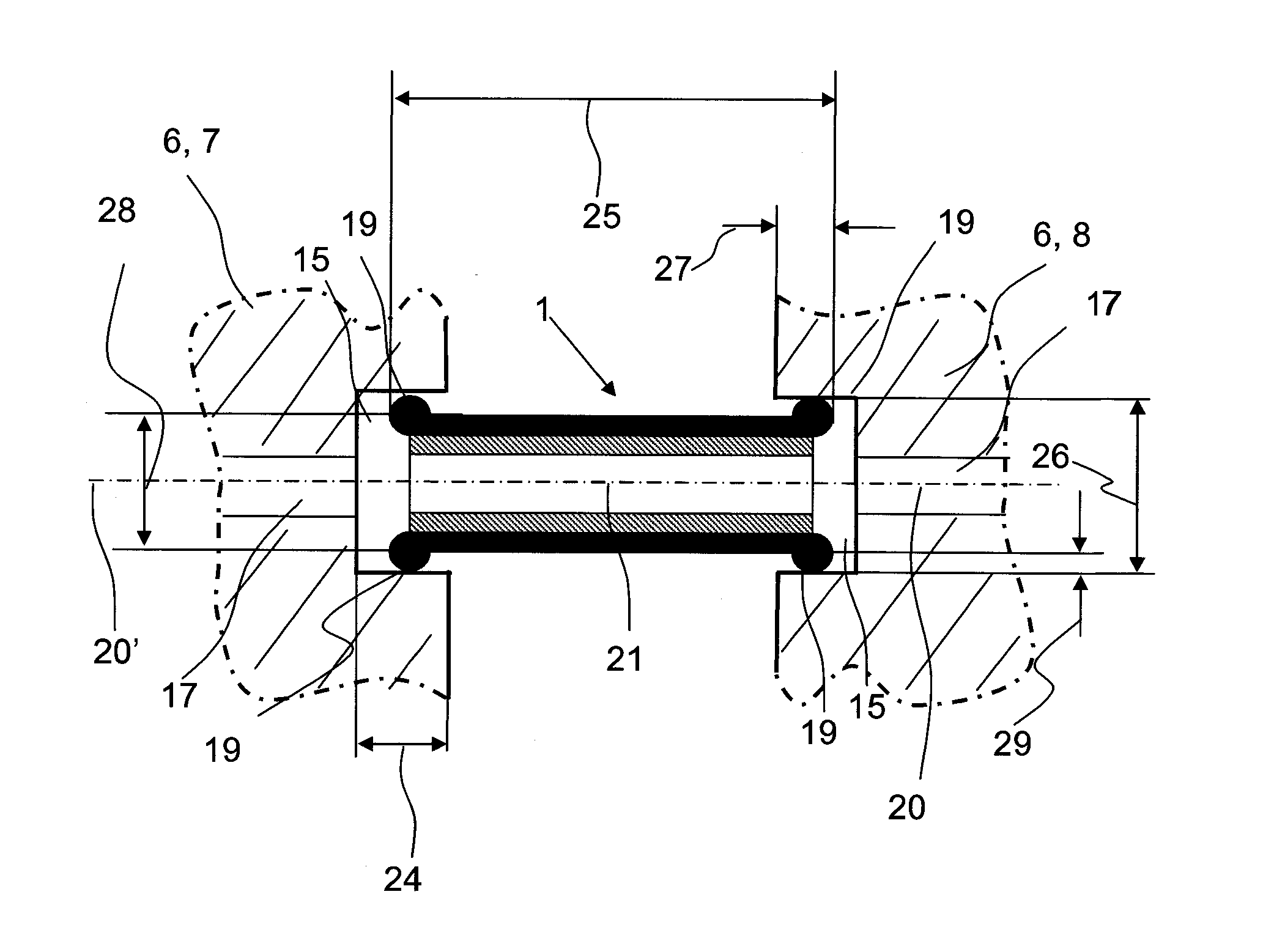
The second exemplary embodiment according to FIG. 4 differs from the first exemplary embodiment of the connection tube 1 only by the geometry of the sealing bead 19. The sealing bead 19 is extended outwardly in the axial direction relative to the inner tube 3, so that an axial sealing surface 16 can also be prepared, besides a radial sealing surface 16, by means of the sealing bead 19. The second exemplary embodiment otherwise corresponds to the first exemplary embodiment according to FIG. 3. Identical components in the second exemplary embodiment according to FIG. 4 are the same as in the first exemplary embodiment according to FIG. 1 and are designated by the same reference numbers as in FIG. 1.

third exemplary embodiment

The third exemplary embodiment according to FIG. 5 differs from the first exemplary embodiment according to FIG. 3, in turn, only in the geometry of the sealing bead 19. The sealing bead 19 is axially extended and radially offset inwardly relative to the inner tube 3, so that only an axial sealing surface 16 can be prepared as a result by means of the sealing bead 19 in recess 15. The third exemplary embodiment according to FIG. 5 otherwise corresponds to the first exemplary embodiment of the connection tube 1 according to FIG. 3. Identical components in the third exemplary embodiment according to FIG. 5 are the same as in the first exemplary embodiment according to FIG. 1 and are designated by the same reference numbers as in FIG. 1.

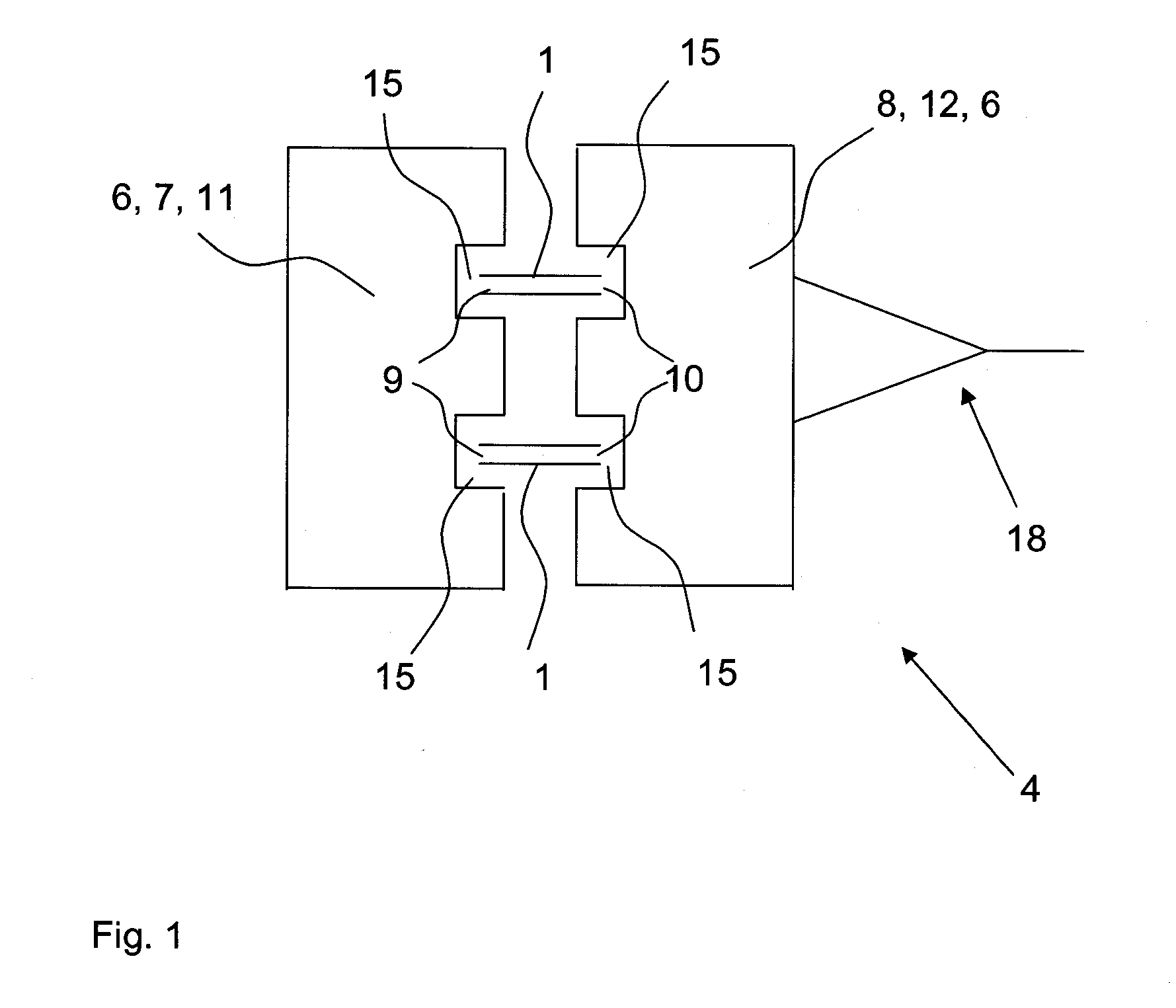
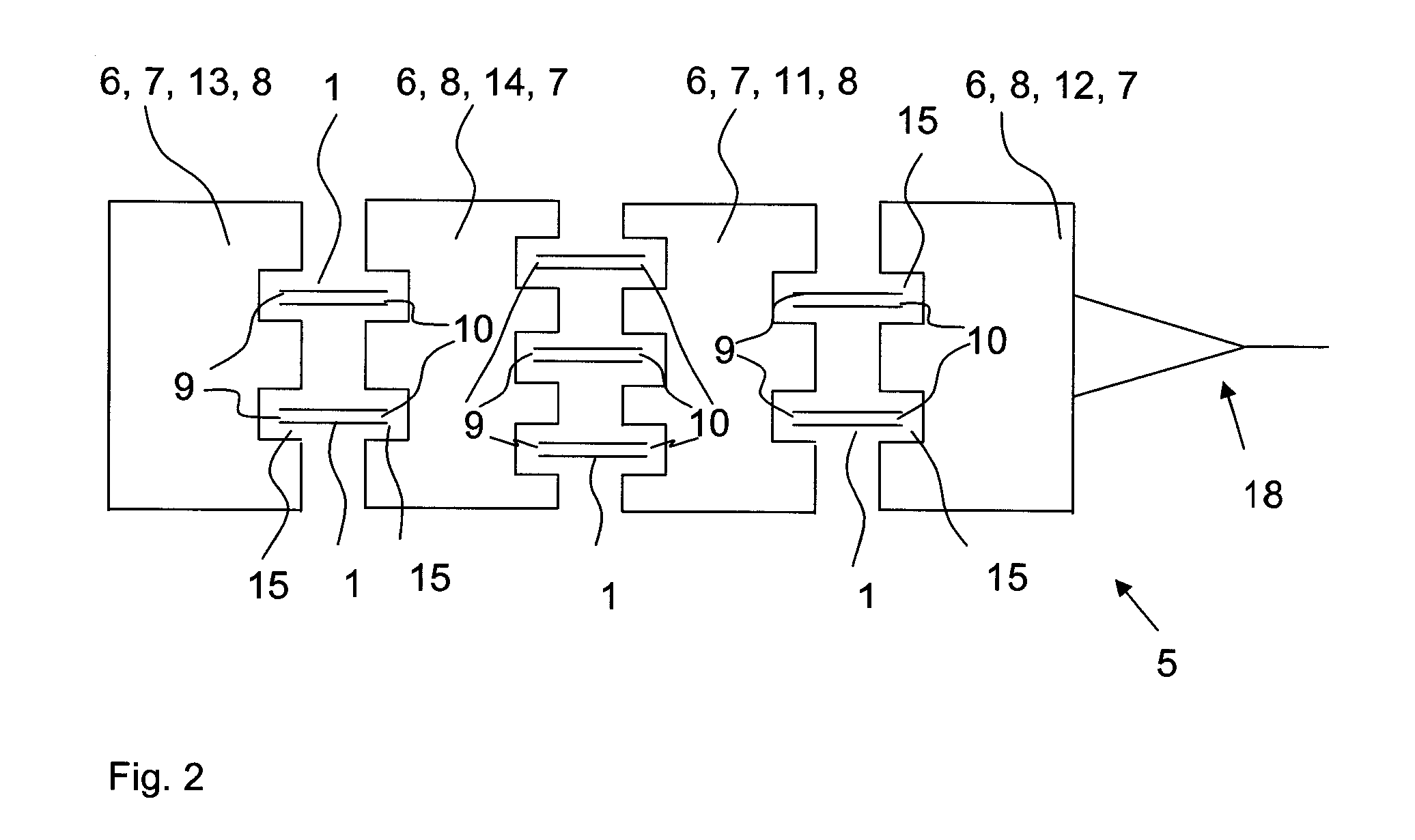
FIGS. 6a through 10 show five different mounting situations of a first and second module 7, 8 with two connection tubes 1 each. The connection tubes 1 with sealing beads 19 are arranged in recesses 15 of the modules 7, 8 and connect the air lines 17 of ...


PUM


Abstract

A pneumatic connection for connecting two modules (6) with one another into a simple and reliable pneumatic connection of modules (6) of the respirator or anesthesia apparatus (5). A small installation space needed is provided in a respirator or anesthesia apparatus (5), including at least two modules (6), e.g., a blower, a breathing system, a mixer and/or an anesthetic evaporator (11, 12, 13, 14). The at least one pneumatic connection includes a connection tube (1), which is surrounded with a first end (9) by a first module (7) and with a second end (10) by a second module (8), so that there is a pneumatic connection through the connection tube (1) between the first module (7) and second module (8). The reliable pneumatic connection is also established when the modules (6) have an offset in their alignment in relation to one another.

Description

CROSS REFERENCE TO RELATED APPLICATIONSThis application claims the benefit of priority under 35 U.S.C. §119 of German Patent Application DE 10 2010 004 527.6 filed Jan. 14, 2010, the entire contents of which are incorporated herein by reference.FIELD OF THE INVENTIONThe present invention pertains to a respirator or anesthesia device comprising at least two modules, e.g., a blower, a breathing system, a mixer and / or an anesthetic evaporator and at least one pneumatic connection for the pneumatic connection of two modules.BACKGROUND OF THE INVENTIONRespirators and anesthesia apparatuses are used in medical technology for the artificial respiration of patients and administering anesthesia to patients. The respirators and anesthesia apparatuses comprise here a plurality of modules, which are connected to one another in a pneumatically gastight manner by means of a pneumatic connection means. The modules are, for example, a blower, a mixer, an anesthetic evaporator or a breathing system....

Claims


Application Information

Patent Timeline
Patent Type & Authority Applications(United States)
IPC IPC(8): A61M16/01
CPCA61M16/0816
Inventor KHOLTCHANSKI, GRIGORYLISCHINSKI, ROBERTPASDZIOR, SVENRADOMSKI, KLAUSREICHERT, DIRK-STEFAN
Owner DRAGERWERK AG
Why Eureka
Try Eureka