
Crane spreader and method for automatically landing the same

a technology of automatic landing and crane, which is applied in the direction of cranes, travelling cranes, load-engaging elements, etc., can solve the problems of difficult to accurately control the relative position of the spreader with respect to the container, take a lot of operation time to engage the spreader with the container, and difficult to accurately control the relative position therebetween

Inactive Publication Date: 2011-06-30
KOREA ADVANCED INST OF SCI & TECH
View PDF22 Cites 16 Cited by
  • Summary
  • Abstract
  • Description
  • Claims
  • Application Information

AI Technical Summary

Benefits of technology

[0015]The present invention provides an apparatus and method which is capable of precisely adjusting the position of a container with respect to a head block connected to a trolley, after the container is engaged with a crane spreader.
[0016]Further, the present invention provides an apparatus and method which is capable of precisely adjusting the position of a spreader with respect to a head hock connected to a trolley, before landing the spreader onto a container.

Problems solved by technology

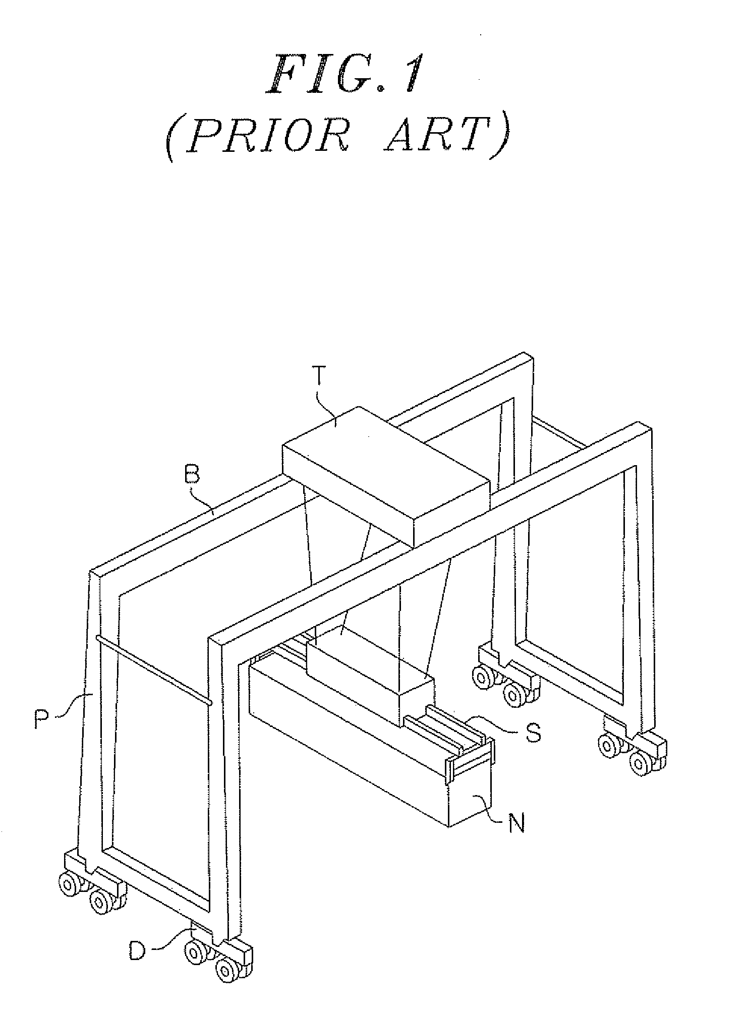
However, in such a conventional container crane, it is difficult to accurately control the relative position of the spreader with respect to the container, because of external factors in which an anchored container vessel pitches or rolls or the spreader suspended to the trolley sways in the wind.
Therefore, when the position of the container or the spreader is swayed by an external factor, it is very difficult to accurately control the relative position therebetween.
As a result, it takes a lot of operation time to engage the spreader with the container and the operation efficiency decreases.
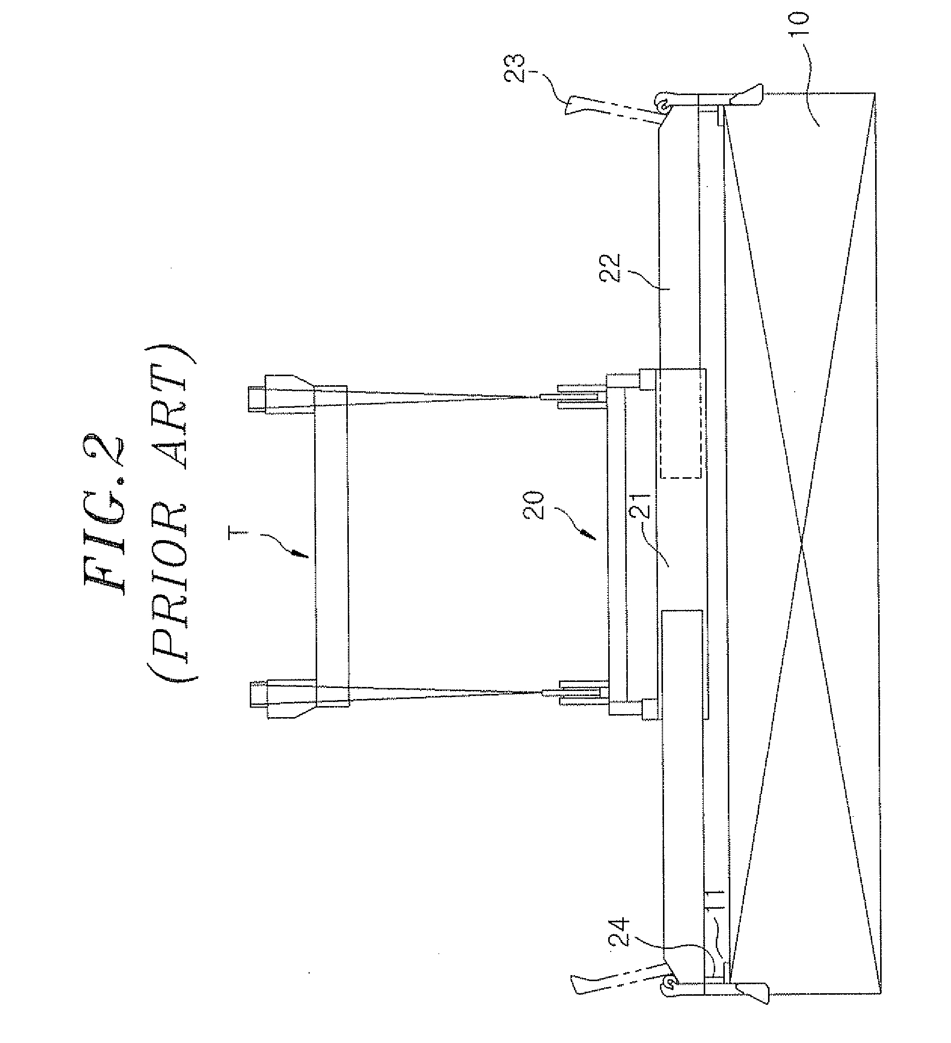
However, in accordance with the above apparatus in which the head block is fixed so as not to relatively move with respect to the frame unit, there is a problem in that the relative position movement between the head block and the container is impossible after the crane spreader is engaged with the container.

Method used


Image

  • Crane spreader and method for automatically landing the same
  • Crane spreader and method for automatically landing the same
  • Crane spreader and method for automatically landing the same

Examples


Embodiment Construction

[0030]Hereinafter, embodiments of the present invention will be described in detail with reference to the accompanying drawings so that they can be readily implemented by those skilled in the art.

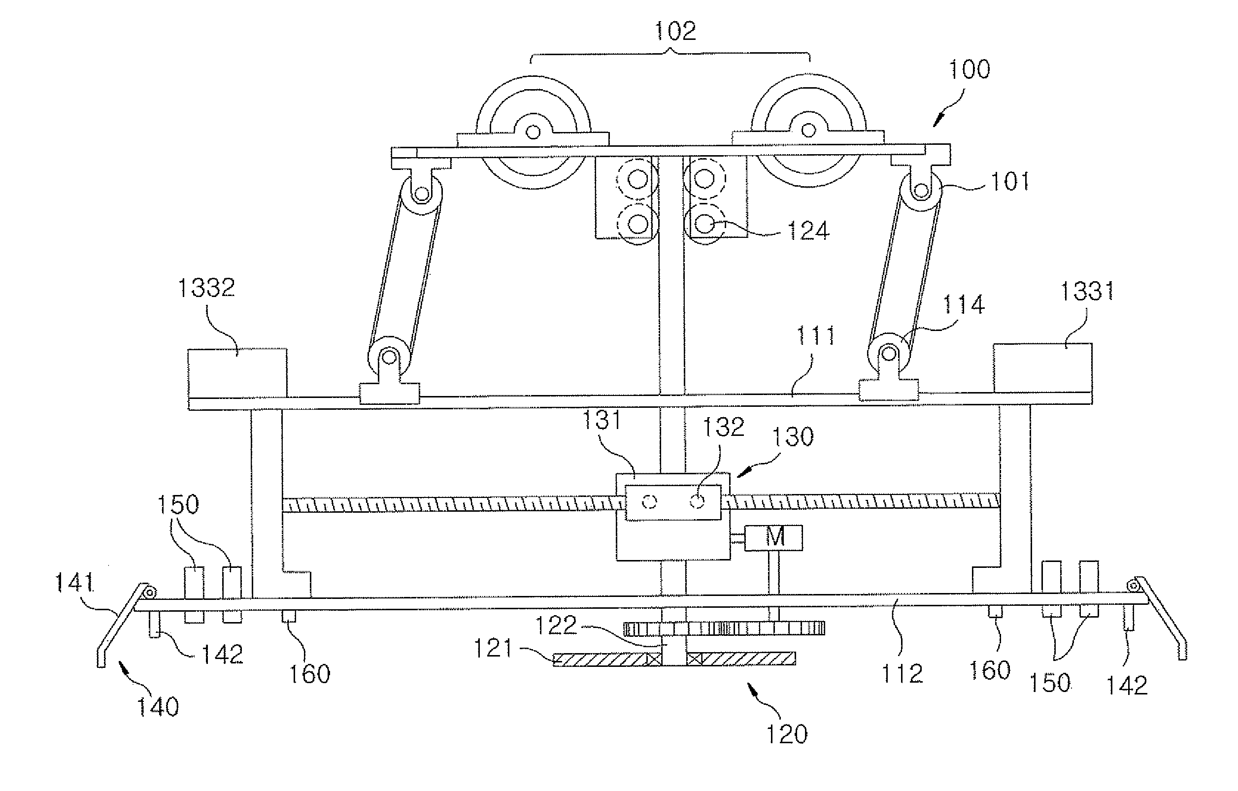
[0031]FIG. 3 is a front view of a crane spreader in accordance with an embodiment of the present invention. FIG. 4 is a perspective view of the crane spreader of FIG. 3. FIG. 5 is a plan view illustrating a position adjustment unit of the crane spreader. FIGS. 6 and 7 are plan views illustrating a process in which the crane spreader in accordance with the embodiment of the present invention is aligned with a container. FIG. 8 is a diagram illustrating a state in which a head block is relatively moved with respect to the container after the crane spreader is coupled to the container. FIG. 9 is a diagram illustrating a state in which a frame unit is relatively moved with respect to the head block after the crane spreader is coupled to the container.

[0032]Referring to FIGS. 3 and 4, the crane ...


PUM


Abstract

A crane spreader for use in lifting a container includes an attachment unit, a head block, a frame unit, a position adjustment unit and a fixation unit. The attachment unit detachably attaches the crane spreader to an upper surface of the container. The head block has a pulley connected to a trolley of a crane through a cable and coupled to the attachment unit to restrict a horizontal movement the attachment unit with respect to the head block. The frame unit is supported by the head block to be horizontally movable with respect to the head block, the frame unit being disposed below the head block with a gap therebetween. The position adjustment unit aligns the frame unit with the container by displacing the frame unit with respect to the attachment unit. The fixation unit engages the container with the frame unit.

Description

FIELD OF THE INVENTION[0001]The present invention relates so a crane spreader and a method for automatically landing the same; and, more specifically, to a crane spreader and an auto landing method which is capable of accurately and quickly landing the crane spreader which is swayed by various external factors.BACKGROUND OF THE INVENTION[0002]As the volume of trade between countries or between cities significantly increases, the traffic volume is also increasing. In particular, a traffic volume through a sea route where the shipping cost is low is rapidly increasing. With such a rapid increase of traffic volume, an ultra large vessel such as a 10,000 TEU vessel has emerged, which is capable of loading a large volume of cargo. Furthermore, the scale of a container terminal is gradually increasing enough to berth such an ultra large vessel. Such a container terminal includes a plurality of large cranes installed therein, which are capable of loading and unloading containers on and fro...

Claims


Application Information

Patent Timeline
IPC IPC(8): B66C1/42B66C23/52
CPCB66C1/101B66C13/46B66C1/663B66C13/14B66C13/16B66C13/22B66C17/04
Inventor KIM, SOO HYUNKIM, EUN HOJANG, IN GWUNJUNG, YUNSUBJU, HANJONGKWAK, YOON KEUNKWAK, BYUNG MANKWAK, KYUNG WOONKOH, DOO YEOLYOO, SANG JUNKIM, JUNGHONG, YUN SIC
Owner KOREA ADVANCED INST OF SCI & TECH
Learn More