
Sensor Model

a sensor and model technology, applied in the field of sensor models, can solve the problems of difficult to continuously accurate measurement in the wye, harsh environment for the sensor, and the ventilator circui

Inactive Publication Date: 2011-06-23
TYCO HEALTHCARE GRP LP
View PDF102 Cites 139 Cited by
  • Summary
  • Abstract
  • Description
  • Claims
  • Application Information

AI Technical Summary

Benefits of technology

[0007]b) extracting respiratory mechanics of the patient from ventilator data by fitting a curve based on at least one of the ventilator settings, the internal measurements, the available hardware characteristics, and the patient characteristics, wherein said fitting relies on one or more fit parameters, and wherein the values of said one or more fit parameters are found by said fitting;
[0008](c) calculating a first estimate of at least one parameter at a patient circuit wye for a time interval with at least one sensor model based on at least one of the ventilator settings, the internal measurements, the available hardware characteristics, the patient characteristics, and the one or more fit parameters; and

Problems solved by technology

However, the ventilator circuit and particularly the patient wye is a challenging environment to make continuously accurate measurements.
The harsh environment for the sensor is caused, at least in part, by the condensations resulting from the passage of humidified gas through the system as well as secretions emanating from the patient.
Over time, the condensate material can enter the sensor tubes and / or block its ports and subsequently jeopardize the functioning of the sensor.
Additionally, inter-patient cross contamination can occur.

Method used


Image

  • Sensor Model
  • Sensor Model
  • Sensor Model

Examples


example

[0080]The following equations express the current discretized implementation of the NPB 840 ventilator for the neonatal patient setting. The variable “n” is equal to interval of measurement. In one embodiment, “n” is used to count discrete intervals of 10 or 5 milliseconds (ms) each. The NPB 840 ventilator utilizes a 5 ms sampling interval and characterizes the components of the tubing including patient circuit resistance and compliance. In this implementation, EQy is assumed negligible.

Py(n)=Pexh(n)+Qc(n)*(K1+K2*Qc(n));

Qc(n)=Qexh(n)+Cef*{dot over (P)}e(n);

{dot over (P)}e(n)=0.185*(Pfe(n)−Pfe(n−1))+0.0745*{dot over (P)}e(n−1)−0.000023*{dot over (P)}e(n−2)

Pfe(n)=0.65*(Pfe(n−1)+0.35*Pe(n); Pfe(0)=0.0

{dot over (P)}y(n)=0.043*((Py(n)−Py(n−1))+0.8714*{dot over (P)}y(n−1)−0.0884*{dot over (P)}y(n−2)

Q1(n)=Qv(n)−m*{dot over (P)}y(n)

Q2(n)=g1*Q2(n−1)+g2*Q1(n)

Qy(n)=A1*Qv(n−1)+A2*Q2(n)−A3*Q2(n−1)

A1=11+0.005*cA2=a*(1+0.005*b)1+0.005*cA3=a1+0.005*c

Model parameters a, b, c, g1, g2, and m are dynam...


PUM


Abstract

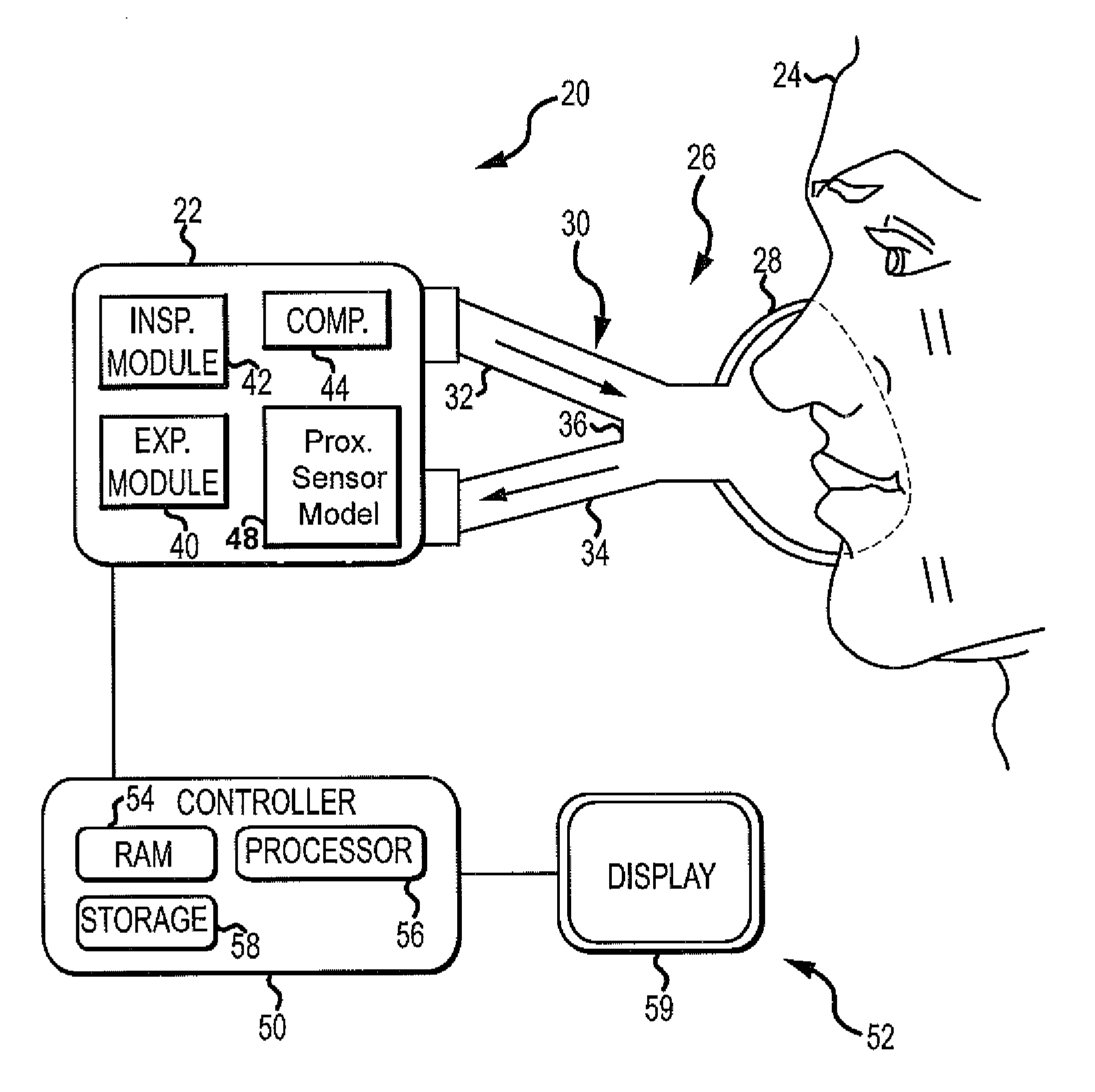
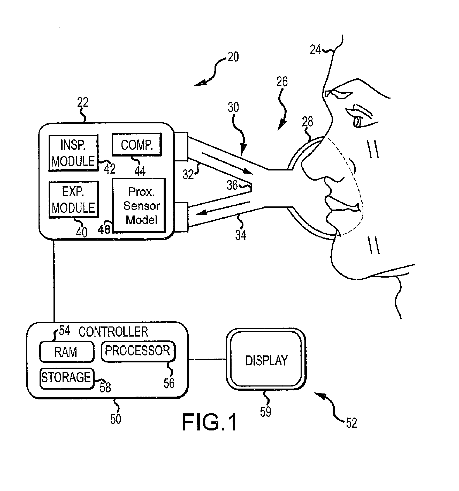
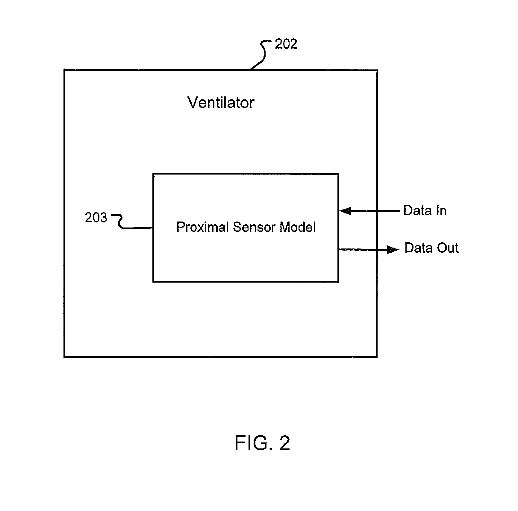
The disclosure describes a novel approach of utilizing a model-based approach for estimating a parameter at the wye without utilizing a sensor at the wye in the circuit proximal to the patient.

Description

RELATED APPLICATIONS[0001]This application is a continuation-in-part of prior application Ser. No. 12 / 643,083, filed Dec. 21, 2009, and entitled “Adaptive Flow Sensor Model” which application is hereby incorporated herein by reference.INTRODUCTION[0002]Medical ventilators may determine when a patient takes a breath in order to synchronize the operation of the ventilator with the natural breathing of the patient. In some instances, detection of the onset of inhalation and / or exhalation may be used to trigger one or more actions on the part of the ventilator. Accurate and timely measurement of patient airway pressure and lung flow in medical ventilators are directly related to maintaining patient-ventilator synchrony and spirometry calculations and pressure-flow-volume visualizations for clinical decision making.[0003]In order to detect the onset of inhalation and / or exhalation, and / or obtain a more accurate measurement of inspiratory and expiratory flow / volume, a flow or pressure sen...

Claims


Application Information

Patent Timeline
Patent Type & Authority Applications(United States)
IPC IPC(8): A61M16/00G06F17/11
CPCA61B5/085A61M16/0051A61M2016/0015A61M2016/0027A61M16/0833A61M2205/17A61M2205/505A61M2205/52A61M2205/702A61M2016/0036A61M16/0063A61M16/026
Inventor JAFARI, MEHDI M.JIMENEZ, RHOMERE S.AVIANO, JEFFREY K.RUSH, RUSSELL P.MCCOY, EDWARD R.UPHAM, GAIL F.
Owner TYCO HEALTHCARE GRP LP
Learn More