
Self-interference cancellation method and apparatus of relay using the same frequency band in ofdm-based radio communication system

a radio communication system and frequency band technology, applied in the field of self-interference cancellation methods and apparatus for relays or repeaters using the same frequency band in an orthogonal frequency division multiplexing (ofdm)based radio communication system, can solve problems such as deteriorating data throughpu

Inactive Publication Date: 2011-06-16
ELECTRONICS & TELECOMM RES INST
View PDF13 Cites 116 Cited by
  • Summary
  • Abstract
  • Description
  • Claims
  • Application Information

AI Technical Summary

Benefits of technology

The patent describes a device and method that can cancel out self-interference in a relay using the same frequency band for transmitting and receiving data. This helps improve the quality of data transmission and reception.

Problems solved by technology

It is referred to as self-interference, which may be a major cause to deteriorate a data throughput.

Method used


Image

  • Self-interference cancellation method and apparatus of relay  using the same frequency band in ofdm-based radio communication system
  • Self-interference cancellation method and apparatus of relay  using the same frequency band in ofdm-based radio communication system
  • Self-interference cancellation method and apparatus of relay  using the same frequency band in ofdm-based radio communication system

Examples


Embodiment Construction

[0020]Reference will now be made in detail to embodiments of the present invention, examples of which are illustrated in the accompanying drawings, wherein like reference numerals refer to the like elements throughout. The embodiments are described below in order to explain the present invention by referring to the figures.

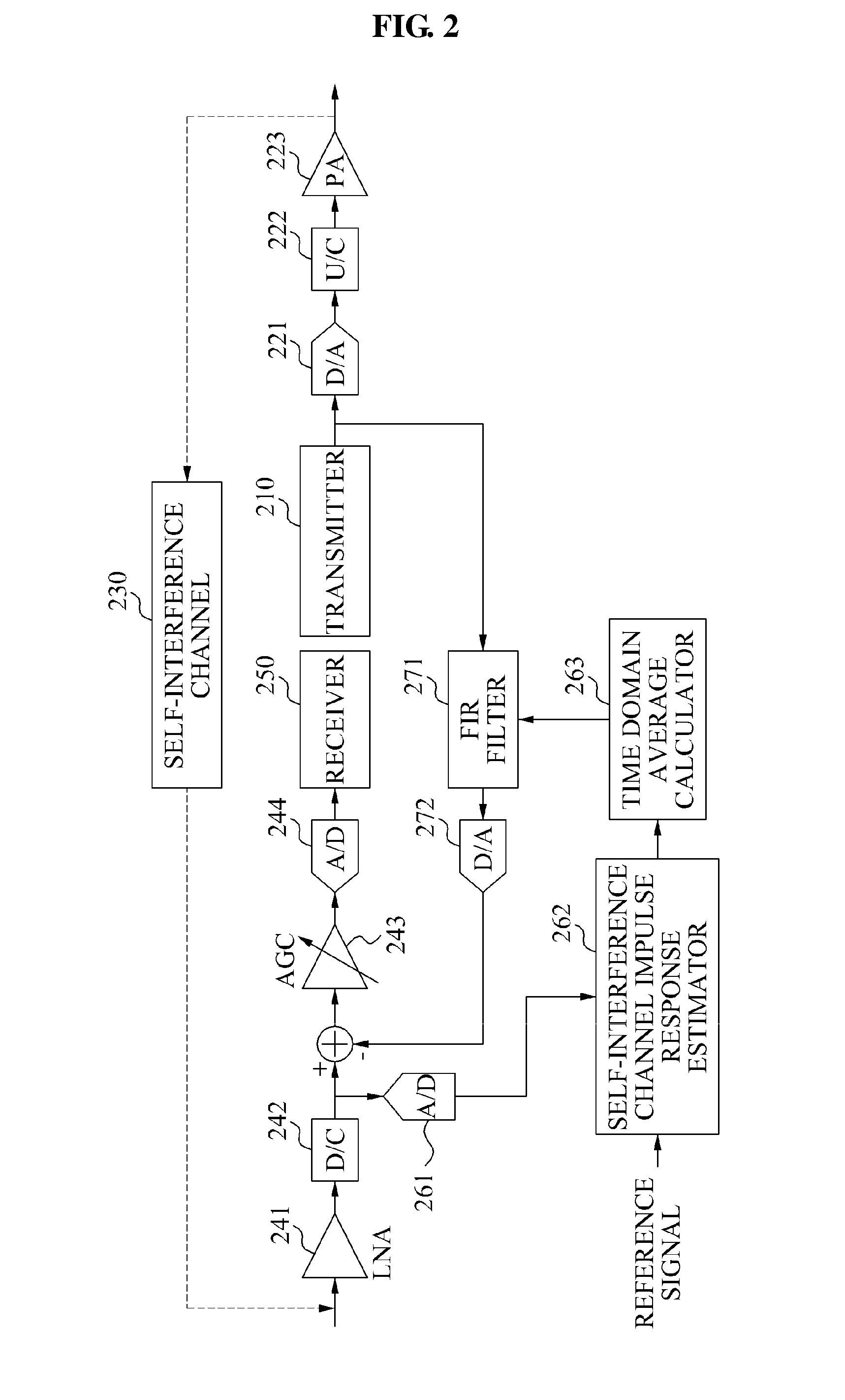
[0021]FIG. 2 is a diagram illustrating a structure of a relay to estimate a self-interference channel 230 in time domain using an open-loop scheme according to an embodiment of the present invention. Referring to FIG. 2, the relay may include a transmitter 210, a receiver 250, a self-interference channel impulse response estimator 262, a finite impulse response (FIR) filter 271, and the like.

[0022]The transmitter 210 may convert data to be transmitted by the relay, to a digital signal. A digital-to-analog (D / A) converter 221 may convert the digital signal to an analog signal. An up-converter 222 may convert the analog signal to a high frequency band signal. A powe...


PUM


Abstract

Provided is a self-interference cancellation method and apparatus that may remove self-interference occurring when a transmission signal of a transmit antenna is received, directly or via a reflector, by a receive antenna in a relay using the same frequency band in an orthogonal frequency division multiplexing (OFDM)-based radio communication system.

Description

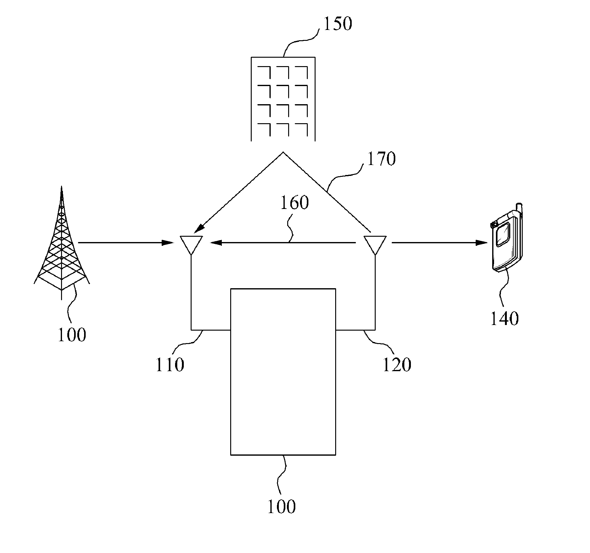
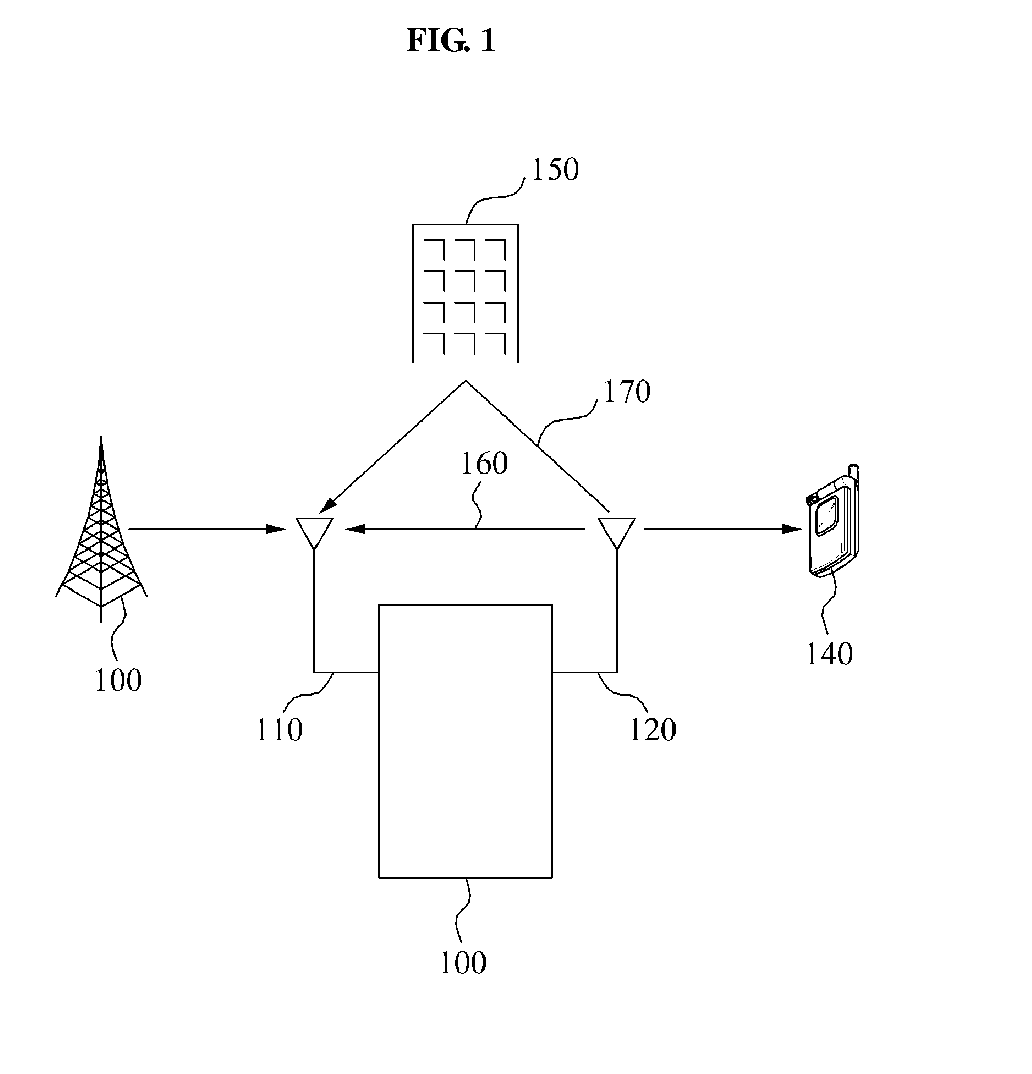
TECHNICAL FIELD[0001]The present invention relates to a self-interference cancellation method and apparatus for a relay or a repeater using the same frequency band in an orthogonal frequency division multiplexing (OFDM)-based radio communication system. More particularly, the present invention relates to a self-interference cancellation method and apparatus that may estimate a self-interference channel between a transmit antenna and a receive antenna of a repeater or a relay by using self-interference that may occur when a transmission signal of the transmit antenna is received, directly or via a reflector, by the receive antenna, and may generate an estimated self-interference using the estimated self-interference channel, and may subtract the generated estimated self-interference from the received signal to thereby cancel the self-interference in the received signal.BACKGROUND ART[0002]FIG. 1 is a diagram for describing self-interference occurring in a relay 100 that transmits fir...

Claims


Application Information

Patent Timeline
Patent Type & Authority Applications(United States)
IPC IPC(8): H04B17/02H04B3/36H04B1/00H04B17/40
CPCH04B7/15542H04L27/2601H04L25/0224H04B7/15585H04B17/345H04B7/14
Inventor AHN, JAE YOUNGKO, YOUNG JOLEE, HEESOO
Owner ELECTRONICS & TELECOMM RES INST
Learn More