
Method And Apparatus For Polarization-Division-Multiplexed Optical Coherent Receivers

Active Publication Date: 2011-06-16
ALCATEL LUCENT SAS
View PDF2 Cites 34 Cited by
  • Summary
  • Abstract
  • Description
  • Claims
  • Application Information

AI Technical Summary

Benefits of technology

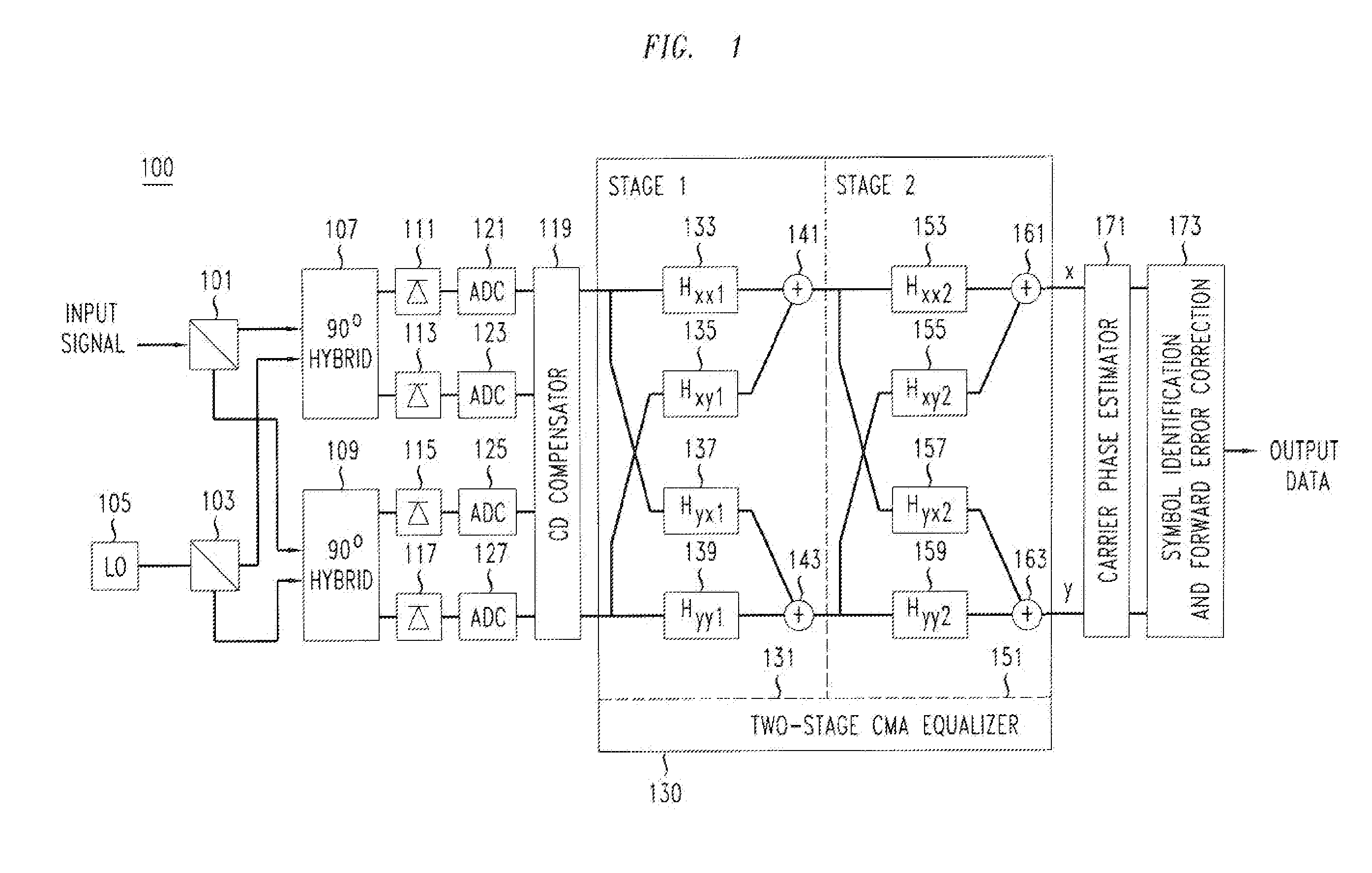
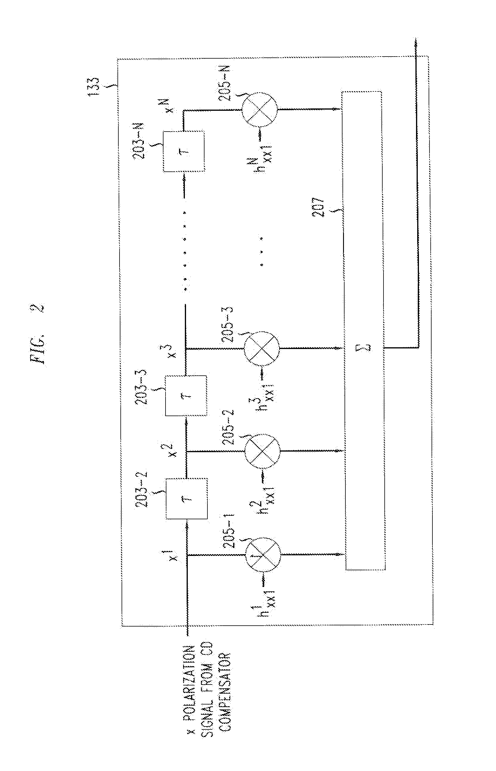
[0008]I have recognized that the singularity problem may be overcome by implementing the constant modulus algorithm (CMA) equalizer that is employed in the receiver as a two-stage equalizer, with the first stage being a modified version of a CMA equalizer and the second stage being a conventional CMA equalizer. For example, in one embodiment of the invention, the first stage modified equalizer is made up of four sub-equalizers, of which only two of the sub-equalizers out of the four are independent, i.e., uncorrelated to each other. This first stage equalizer is employed to compensate for PMD. The second stage equalizer is a conventional CMA equalizer made up of four sub-equalizers that are adjusted independently in the conventional manner. Furthermore, this second stage equalizer compensates for polarization-dependent loss (PDL) and any residual CD that is not fully compensated for by a CD compensator which is before the two-stage equalizer. Advantageously, as the determinant of the first stage never approaches zero, the singularity problem of a conventional CMA single-stage-only equalizer is avoided by the two-stage equalizer.

Problems solved by technology

Unfortunately, the polarization orientations of the generic signal components are generally changed by the birefringence of the fiber, and possibly other fiber properties, during the passage of the signal over the optical path.
Optical communication systems also suffer from polarization dependent loss (PDL).
Unfortunately, such prior art systems suffer from various disadvantages.
804-817, pointed out that the prior art systems suffer from the so-called “singularity problem”, which means that the output two polarization tributaries tend to converge to the same source.

Method used


Image

  • Method And Apparatus For Polarization-Division-Multiplexed Optical Coherent Receivers
  • Method And Apparatus For Polarization-Division-Multiplexed Optical Coherent Receivers
  • Method And Apparatus For Polarization-Division-Multiplexed Optical Coherent Receivers

Examples


Embodiment Construction

[0012]The following merely illustrates the principles of the invention. It will thus be appreciated that those skilled in the art will be able to devise various arrangements that, although not explicitly described or shown herein, embody the principles of the invention and are included within its spirit and scope. Furthermore, all examples and conditional language recited herein are principally intended expressly to be only for pedagogical purposes to aid the reader in understanding the principles of the invention and the concepts contributed by the inventor(s) to furthering the art, and are to be construed as being without limitation to such specifically recited examples and conditions. Moreover, all statements herein reciting principles, aspects, and embodiments of the invention, as well as specific examples thereof, are intended to encompass both structural and functional equivalents thereof. Additionally, it is intended that such equivalents include both currently known equivale...


PUM


Abstract

The singularity problem of the constant modulus algorithm (CMA) equalizer may be overcome by implementing the CMA equalizer as a two-stage equalizer, with the first stage being a modified version of a CMA equalizer and the second stage being a conventional CMA equalizer. The first stage may be made up of four sub-equalizers, of which only two of the sub-equalizers are independent, i.e., uncorrelated to each other. This first stage equalizer may compensate for PMD. The second stage equalizer is a conventional CMA equalizer made up of four sub-equalizers that are adjusted independently. This second stage equalizer may compensate for polarization-dependent loss (PDL) and any residual CD that is not fully compensated for by a CD compensator before the two-stage equalizer. Advantageously, as the determinant of the first stage never approaches zero, the singularity problem of a conventional CMA single-stage-only equalizer is avoided by the two-stage equalizer.

Description

TECHNICAL FIELD[0001]This invention relates to optical communications, and more particularly, to optical communications using polarization-division-multiplexing.BACKGROUND OF THE INVENTION[0002]As is well known, an optical signal may have two orthogonal polarization states, each of which may have different properties. Sometimes such polarization states are intentionally introduced, such as in creating a polarization-multiplexed signal in which the two orthogonal polarization states of the optical carrier are arranged so that each carries different data in order to double the spectral efficiency. Such a polarization-multiplexed signal has two so-called “generic” polarization components, each of which carries a single data modulation. Note that by a generic polarization component it is generally intended the signal at the point at which the modulation of that polarization component is completed. It should be appreciated that each generic polarization component may initially, or otherw...

Claims


Application Information

Patent Timeline
IPC IPC(8): H04J14/06H04B10/06
CPCH04B10/60H04B10/611H04J14/06H04B10/6162H04B10/6161H04B10/65
Inventor XIE, CHONGJIN
Owner ALCATEL LUCENT SAS
Learn More