
Method and device for visualizing surface-like structures in volumetric data sets

Active Publication Date: 2011-05-05
TOMTEC IMAGING SYST
View PDF9 Cites 14 Cited by
  • Summary
  • Abstract
  • Description
  • Claims
  • Application Information

AI Technical Summary

Benefits of technology

[0014]The major advantage of the present invention is that it is not necessary to re-sample the data into a Cartesian geometry, and the present invention also performs much easier and faster calculations, thereby enabling the use of known shading and illumination models.
[0015]The method of the present invention comprises the steps of:
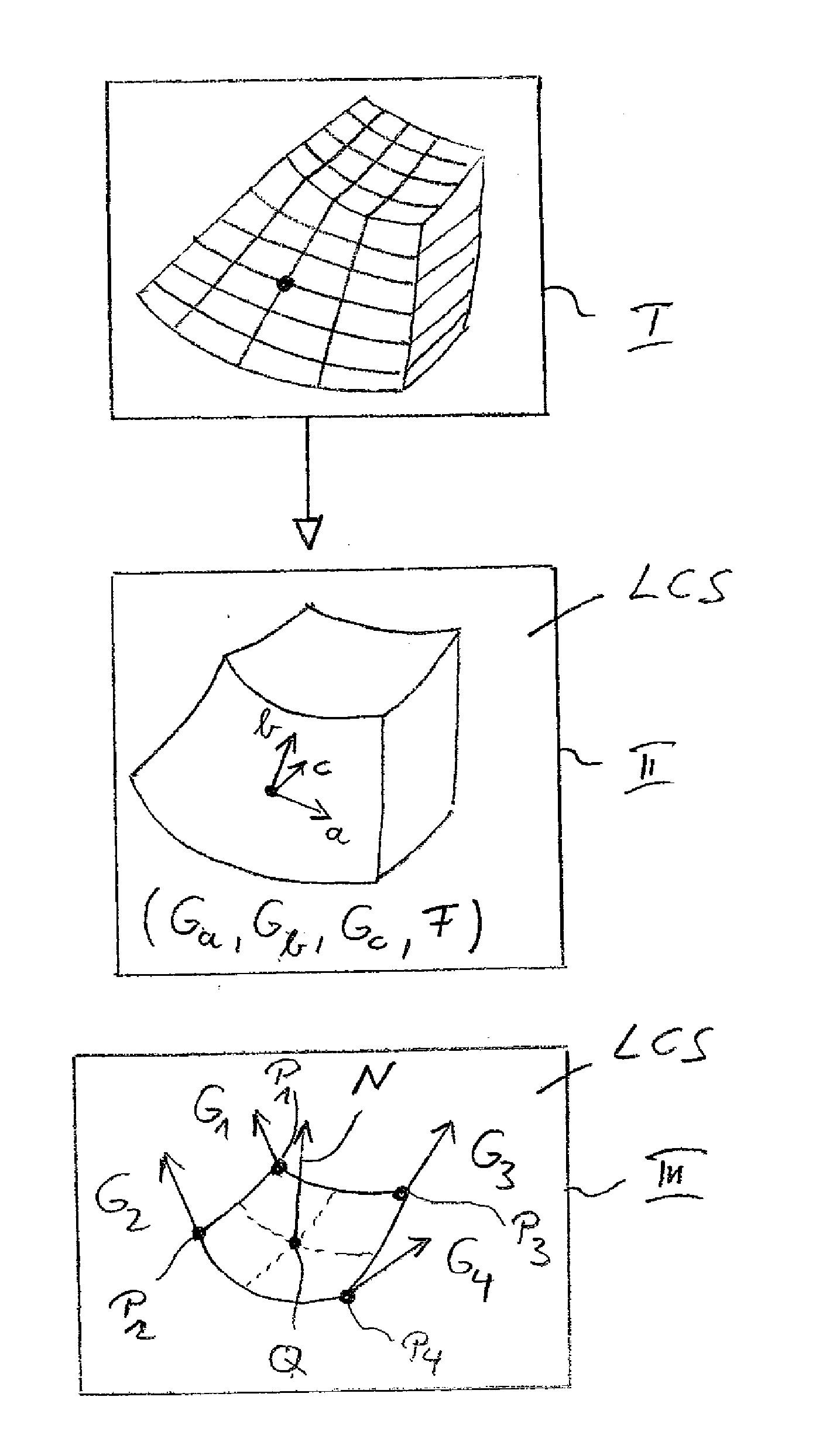
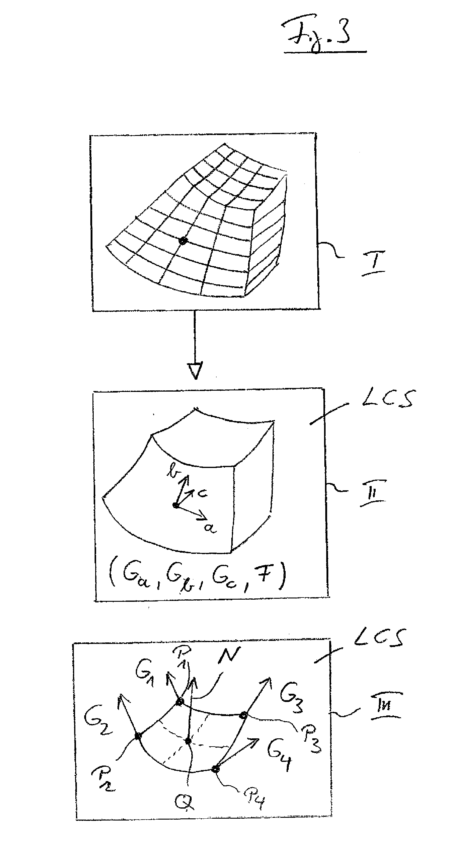
[0016]a) defining local coordinate systems at sample points of said volumetric data set,
[0017]b) calculating the gradient vector components (Gai, Gbi, Gci) within said local coordinate systems of said sample points,
[0018]c) transforming said external parameters from a global coordinate system into said local coordinate systems at selected sample points or at the points of a reference grid, and
[0019]d) using said gradient vector components (Gai, Gbi, Gci) for calculating a surface normal at a given position of said volumetric data set,

Problems solved by technology

The main drawback, however, is the increased data size.
The volume data is expanded by at least the factor 4 which easily becomes a problem on machines with a low amount of memory.
For non-Cartesian data such as ultrasound data, which is e.g. given in so-called acoustic coordinates, it is not possible to directly use models such as Blinn-Phong or the Phong reflection model thereby using the gradient vector as mentioned above at a given sample position, thereby using any of the differencing schemes mentioned above.
The above-mentioned solution requires an expensive re-sampling step to a Cartesian geometry.

Method used


Image

  • Method and device for visualizing surface-like structures in volumetric data sets
  • Method and device for visualizing surface-like structures in volumetric data sets
  • Method and device for visualizing surface-like structures in volumetric data sets

Examples


Embodiment Construction

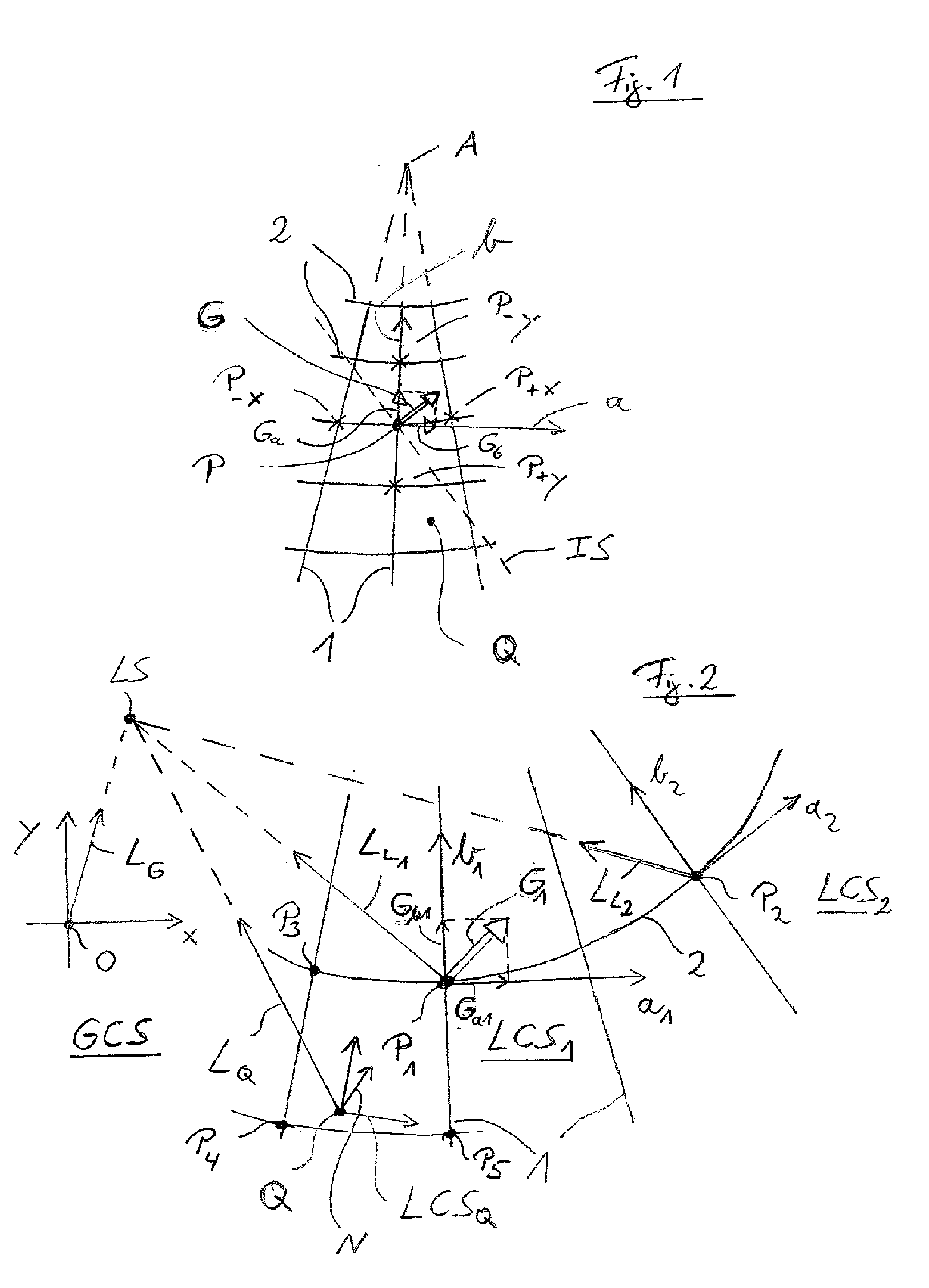
[0055]FIG. 1 shows a conventional ultrasound (acoustic) grid with an apex A, beams 1 and rows 2, wherein beams 1 and rows 2 represent the acoustic coordinate system (e.g. range and azimuth, respectively) in a two-dimensional representation. The third dimension, e.g. the elevation of a spherical coordinate system, is not shown in FIG. 1 for better understanding of the present invention.

[0056]As described above, the local gradient vector G is defined by local gradient vector components Ga and Gb of a sample point P, wherein these components may be calculated by a differencing scheme as mentioned above.

[0057]FIG. 2 schematically shows the transformation of an external parameter, such as a light source LS, from a global coordinate system GCS into local coordinate systems, namely a first local coordinate system LCS1 and a second local coordinate system LCS2, which are defined at a first sample point P1 and a second sample point P2 in an acoustic grid as shown in FIG. 1.

[0058]Each sample ...


PUM


Abstract

The present invention relates to a method and a device for visualizing surface-like structures in volumetric data sets, including defining local coordinate systems at sample points of the volumetric data set, transforming external parameters from a global coordinate system into the local coordinate systems, calculating the gradient vector components (Gai, Gbi, Gci) within the local coordinate systems of the sample points, and using the gradient vector components (Gai, Gbi, Gci) for calculating a surface normal at a given position of the volumetric data set, where the surface normal is important for conventional illumination models such as the Blinn-Phong shading model, preferably, the present invention is also calculating the external parameters from the global coordinate system at the given position by using the transformed external parameters of the local coordinate systems of the sample points, where the shading or illumination at the given position is then done by using a conventional illumination model, thereby using the calculated surface normal at the given position and the calculated external parameters at the given position.

Description

TECHNICAL FIELD[0001]The present invention relates to a method and a device for visualizing surface-like structures in volumetric data sets, such as volume rendering, especially for illuminating these surface-like structures, especially for real-time rendering of sampled data from ultrasound data acquisition. The present invention specifically relates to three-dimensional medical imaging, where two-dimensional images are volume-rendered from three-dimensional data volumes.BACKGROUND[0002]Three-dimensional ultrasound imaging but also CT or MR imaging generates three-dimensional data which is usually formatted in a coordinate system which is not a Cartesian coordinate system. Such non-Cartesian grid is e.g. an acoustic grid of an ultrasound probe which obtains images of e.g. the heart of a human being. Such data, which represents a volume, is usually scan-converted along the Cartesian coordinate system before being volume-rendered. When displaying the object scanned, it is necessary t...

Claims


Application Information

Patent Timeline
IPC IPC(8): G06T17/00
CPCG06T15/50G06T15/08
Inventor BRABEC, STEFAN
Owner TOMTEC IMAGING SYST
Learn More