
Gingival retraction system

a technology of gingival retraction and retraction cord, which is applied in the field of system and method of retraction of gingival tissue within, can solve the problems of damage and bleeding, difficult to place retraction cord through the spaces between adjacent teeth, and difficult to place known gingival retraction cords before tooth preparation

Inactive Publication Date:
View PDF19 Cites 7 Cited by
  • Summary
  • Abstract
  • Description
  • Claims
  • Application Information

AI Technical Summary

Benefits of technology

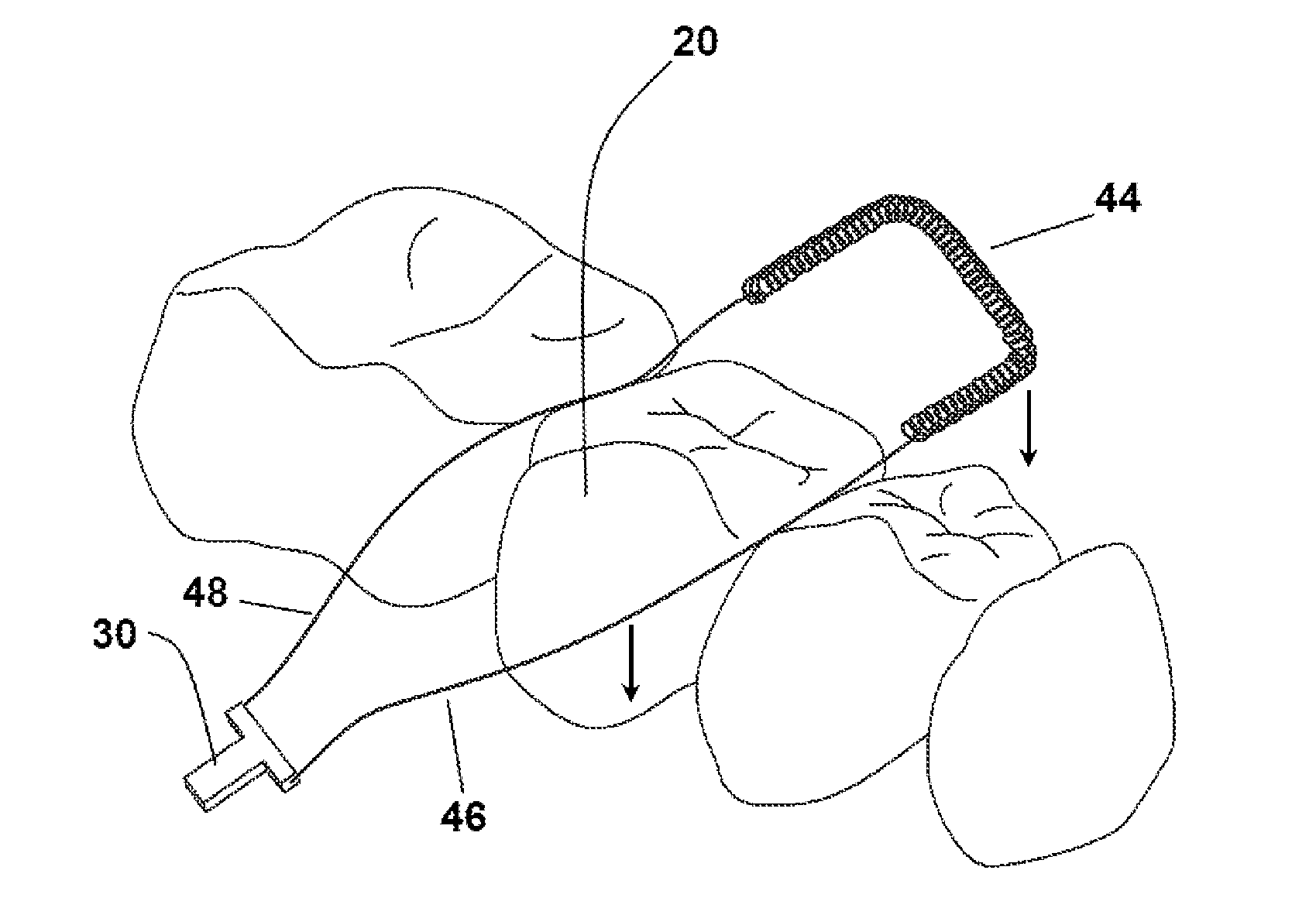
In an additional aspect, the handle of the gingival retraction system is attached to the first lead portion and the second lead portion. In another aspect, the handle is configured for selective movement by a dental practitioner until the retraction portion is securely positioned within the gingival sulcus proximate the damaged tooth. In a further aspect, the handle has a cutting mechanism for trimming portions of the gingival retraction cord that are not required to secure the retraction portion within the gingival sulcus. In still a further aspect, the handle can be reusable. Alternatively, the handle can be disposable.

Problems solved by technology

During the tooth preparation procedure, dental instruments can contact gingival tissue, causing damage and bleeding.
Due to the thicknesses of known gingival retraction cords, it is difficult to position retraction cords through the spaces between adjacent teeth from the occlusal toward the gingiva, through the “contact area” defined by adjacent teeth, and then within the gingival sulcus.
Thus, it is often challenging to place known gingival retraction cords before preparation of a tooth has begun.
Before preparing the margin, it can be difficult and time-consuming to horizontally direct a retraction cord into the gingival sulcus, and this can subject the gingival tissue to trauma.
In some cases, the position of the gingiva can be so close to the tooth surface and tooth margin area that preparation of the margin before placement of the cord risks contacting the gingiva with preparation instruments, which can cause gingival damage and bleeding.
Due to the uniform thicknesses of many known gingival retraction cords, the cords are often inadequately sized to be both easily positioned through the contact area between the teeth and to effectively retract the gingiva around the gingival sulcus.
If a gingival retraction cord is thick enough to retract the gingiva, it is often too thick to slide through the contact area between the teeth.
Similarly, if a gingival retraction cord is thin enough to slide through the contact area, it is often too thin to effectively retract gingival tissue.
Moreover, during placement of known gingival retraction cords after a tooth margin has been fully or partially prepared, the material of the gingival retraction cords often have a tendency to become caught after contacting the margins of the tooth.
Further, positioning of known gingival retraction cords frequently requires a dental practitioner to use many repetitive steps or poking movements with a cord packing instrument that are time consuming and can cause injury or bleeding in the gingiva surrounding the tooth.
Cutting the proper length of cord and securing the ends in the gingival sulcus can also be time-consuming and can injure the gingiva.
Trimming excess portions of gingival retraction cords can cause unnecessary delays in the time required to secure the gingival retraction cord within the gingival sulcus.

Method used


Image

  • Gingival retraction system
  • Gingival retraction system
  • Gingival retraction system

Examples


Embodiment Construction

The present invention can be understood more readily by reference to the following detailed description, examples, drawing, and claims, and their previous and following description. However, before the present devices, systems, and / or methods are disclosed and described, it is to be understood that this invention is not limited to the specific devices, systems, and / or methods disclosed unless otherwise specified, as such can, of course, vary. It is also to be understood that the terminology used herein is for the purpose of describing particular aspects only and is not intended to be limiting.

The following description of the invention is provided as an enabling teaching of the invention in its best, currently known embodiment. To this end, those skilled in the relevant art will recognize and appreciate that many changes can be made to the various aspects of the invention described herein, while still obtaining the beneficial results of the present invention. It will also be apparent...


PUM


Abstract

A gingival retraction system for retracting gingival tissue surrounding a selected tooth within the mouth of a subject is disclosed. In one aspect, the gingival retraction system has a gingival retraction cord and a handle. The gingival retraction cord has at least one lead portion and at least one retraction portion. Portions of the gingival retraction cord are positioned within the gingival sulcus surrounding the selected tooth. The handle can be used to tighten and shorten the portion of the gingival retraction cord positioned within the gingival sulcus surrounding the selected tooth.

Description

FIELD OF THE INVENTIONThis invention relates to a system and method for retracting gingival tissue within the mouth of a subject. More specifically, this invention relates to a system and method for retracting gingival tissue surrounding a tooth of a subject prior to initiating a tooth preparation procedure as part of a dental restoration.BACKGROUND OF THE INVENTIONIn dental therapeutics, a damaged tooth is prepared for receiving an artificial crown or onlay or inlay or other dental restoration by removal of portions of the tooth with a high-speed drill or other instrument. The junction where the uncut, more apical portion of the tooth meets the cut, more coronal portion of the tooth is commonly referred to as the “margin” of the tooth. An artificial crown is fabricated based on an impression of the tooth, including the margin of the tooth, the gingival tissue surrounding the tooth, and the area between the tooth and the gingival tissue surrounding the tooth (“the gingival sulcus” o...

Claims


Application Information

Patent Timeline
Patent Type & Authority Applications(United States)
IPC IPC(8): A61C5/14
CPCA61C9/0033
Inventor ROSS, DON
Learn More