
Method and apparatus for decoding video signal

a video signal and decoding technology, applied in signal generators with optical-mechanical scanning, color televisions with bandwidth reduction, signal systems, etc., can solve problems such as recovery rate deterioration, and achieve the effect of increasing the coding efficiency of video signals

Active Publication Date: 2011-04-21
LG ELECTRONICS INC
View PDF11 Cites 146 Cited by
  • Summary
  • Abstract
  • Description
  • Claims
  • Application Information

AI Technical Summary

Benefits of technology

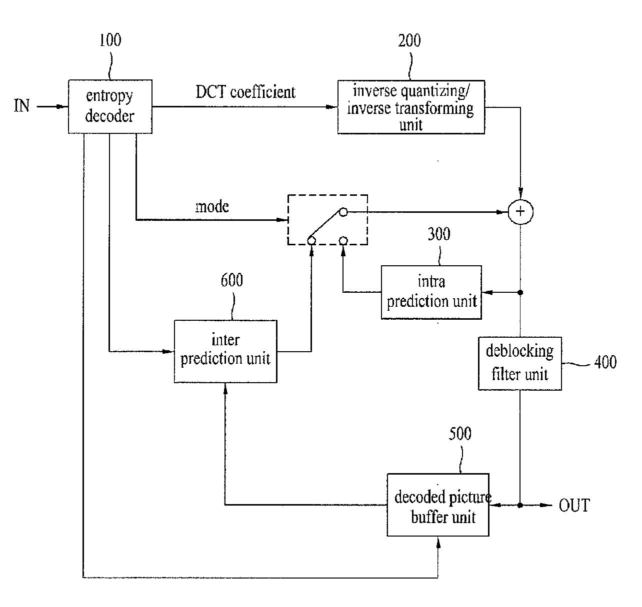
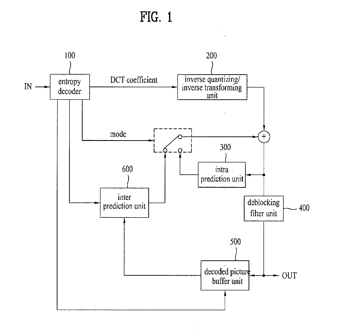
[0009]An object of the present invention is to provide a method and apparatus for decoding a video signal so as to increase coding efficiency of the video signal.

Problems solved by technology

In addition, if the spatial redundancy and the temporal redundancy are excessively removed, it is impossible to generate information required for decoding the video signal, resulting in deterioration of a recovery rate.

Method used


Image

  • Method and apparatus for decoding video signal
  • Method and apparatus for decoding video signal
  • Method and apparatus for decoding video signal

Examples


Embodiment Construction

[0030]Reference will now be made in detail to the preferred embodiments of the present invention, examples of which are illustrated in the accompanying drawings. Wherever possible, the same reference numbers will be used throughout the drawings to refer to the same or like parts. Specific terms used for the exemplary embodiments of the present invention are provided to aid in understanding of the present invention. These specific terms may be replaced with other terms within the scope and spirit of the present invention.

[0031]A bitstream of a video signal is defined as a separated hierarchical layer structure that is called a Network Abstraction Layer (NAL) located between a Video Coding Layer (VCL) for handling motion image coding processing and a lower system for transmitting and storing coded information. The coding process outputs VCL data as an output signal, and is mapped in units of an NAL prior to the transmitting or storing of data. Each NAL unit includes a Raw Byte Sequenc...


PUM


Abstract

A method and apparatus for decoding a video signal are disclosed. A method for decoding a video signal includes obtaining block type information of a current block, confirming a prediction mode of the current block based on the block type information, obtaining, if the prediction mode of the current block is an intra prediction mode according to the prediction mode, at least one correlation parameter information using at least one neighboring pixel of the current block, obtaining an intra prediction value of the current block using the correlation parameter information, and reconstructing the current block using the intra prediction value of the current block.

Description

[0001]This application claims the benefit of the U.S. provisional Application Nos. 61 / 051,343 and 61 / 102,012 filed on May 7, 2008 and Oct. 2, 2008, respectively, which are hereby incorporated by reference as if fully set forth herein.[0002]This application also claims the benefit of Koran patent application No. 10-2009-0039683 filed on May 7, 2009, respectively, which is hereby incorporated by reference as if fully set forth herein.BACKGROUND OF THE INVENTION[0003]1. Field of the Invention[0004]The present invention relates to a method and apparatus for decoding a video signal.[0005]2. Discussion of the Related Art[0006]Generally, compression coding indicates a series of signal processing technologies which can transmit digitized information through a communication line or can store the digitized information in a specific form suitable for a storage medium. A variety of objects can be compression-coded, for example, sound data, image (or video) data, text data, etc. Particularly, te...

Claims


Application Information

Patent Timeline
IPC IPC(8): H04N7/26H04N19/593
CPCH04N19/105H04N19/176H04N19/61H04N19/593H04N19/86H04N19/157H04N19/182H04N19/44H04N19/14H04N19/11H04N19/159H04N19/164H04N19/46
Inventor SUNG, JAE WONPARK, SEUNG WOOKJEON, YONG JOONKIM, JUNG SUNCHOI, YOUNG HEEJEON, BYEONG MOONPARK, JOON YOUNG
Owner LG ELECTRONICS INC
Learn More