Eureka AIR delivers breakthrough ideas for toughest innovation challenges, trusted by R&D personnel around the world.

Combination solar and dual generator wind turbine

Inactive Publication Date: 2011-04-21
AHMADI WILLIAM
View PDF18 Cites 53 Cited by
  • Summary
  • Abstract
  • Description
  • Claims
  • Application Information

AI Technical Summary

Benefits of technology

An object of the invention is to provide a dual aligned synchronized generator variable speed direct drive turbine topped by a photo-voltaic panel. Each generator may be composed of mini shafts whereby neither of the shafts run through the center of the turbine, which traditional turbines have. Instead, the shafts from the generators are connected to the ends of the central column of the turbine running through both generators. The turbine may also include a traditional central shaft. The turbines create mechanical energy whereby the generators convert said mechanical energy into an electrical energy source. A storag

Problems solved by technology

The use of wind energy is a viable substitute and alternative, and generally costly, however recent developments in the art point to a future of increased usage and lower costs overall.
The benefits of wind and solar energy cannot be underestimated.
For example, the use of pit mining brings with it inherent risks to mine workers health and CO2 emissions caused by burning coal.
Lastly today's standard turbine blade is heavy, large and costly, three major reasons why the use of wind as an energy source remains minimal relative to its potential.
This may result in a greater airflow across the turbines resulting in greater propeller speeds, however unless the actual design of the traditional blade is fundamentally improved, improvements mentioned above will only achieve minimal success at best.
A fault is a disturbance th

Method used


Image

  • Combination solar and dual generator wind turbine
  • Combination solar and dual generator wind turbine
  • Combination solar and dual generator wind turbine

Examples


Example

DETAILED DESCRIPTION OF THE DRAWINGS

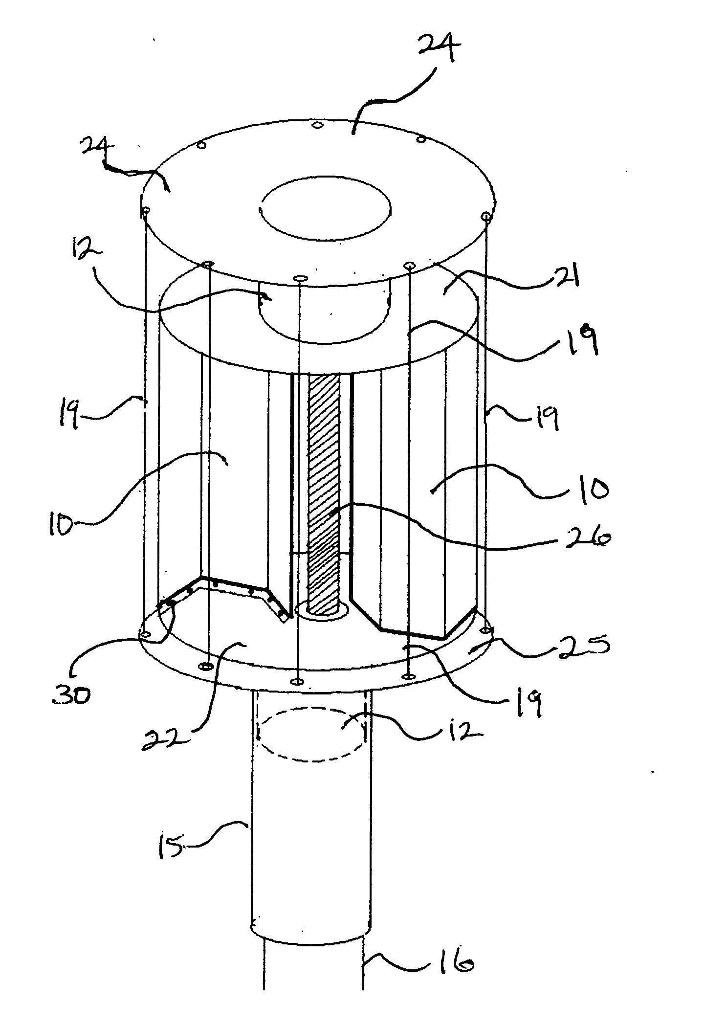
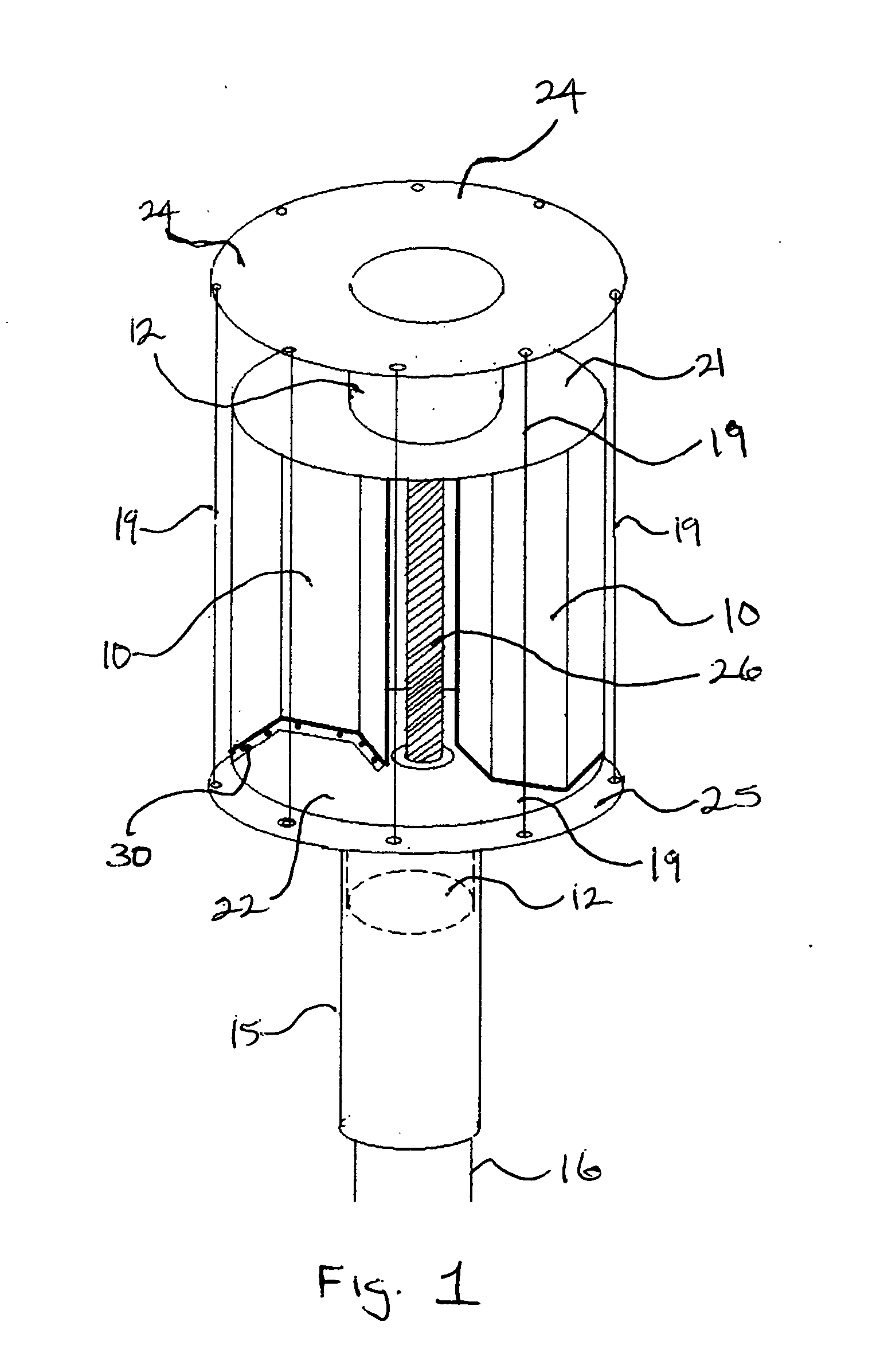
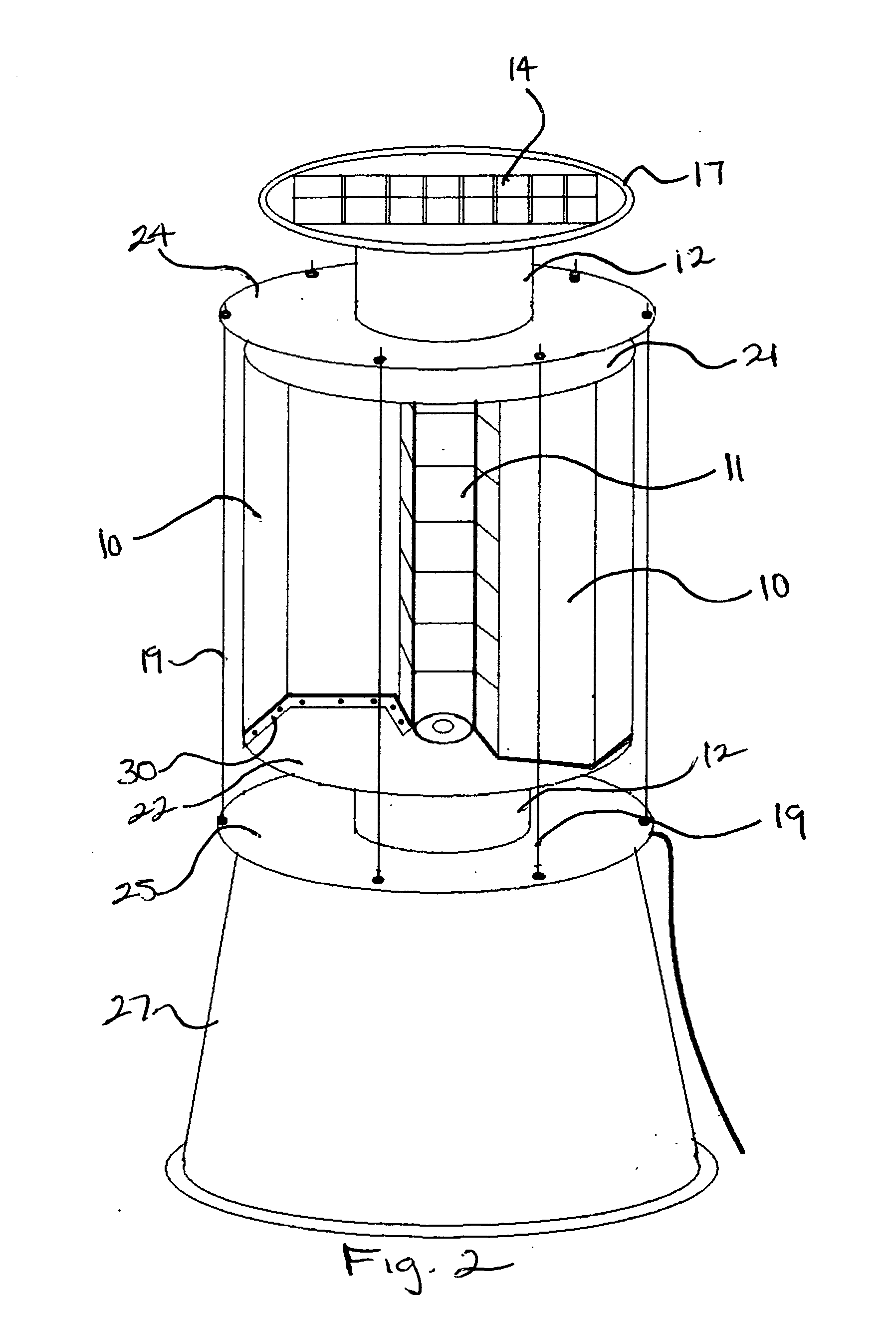
An embodiment of the present invention with a shaft is related in FIG. 1 where a three dimensional sectional view of the wind turbine with a standard shaft is provided. At the base of FIG. 1 attached to the lower body cap 25 is an enclosure for the generator 12 therein. A topside enclosure for a second generator 12 is attached to the upper body cap 24 at the opposing end. The wind turbine is secured to a post which may be of a plurality of sizes, said post consisting of both a male post 16 and female post 15 with an end secured to base generator 12 whereby said generator 12 slides up into the its mounting base matching the circumference of the and secured by nuts and bolts therein. The other end attached to the lower post by treaded nuts and bolts as well. Said lower body cap 25, and upper body cap 24 is circular in dimension and is equal in circumference to that of the surrounding enclosure bars 19 about the surface of the wind turbine. The upper...


PUM


Abstract

A single or dual aligned synchronized generator and variable speed direct drive wind turbine for installation on a wind farm, solar and wind powered self watering farm, building, light post, atop roofs and other mountable locations employs either a vertical or horizontal shaft less wind turbine system. The system takes advantage of low or high wind speed conditions with specially designed geometrically shaped turbine blades of light weight. The hollow center allows the turbine to operate under less weight and stress than traditional turbine systems. The blades are designed to minimize negative forces, stresses and drag. Electrical energy may be stored or directly transmitted to a grid system. In addition the system employs a photovoltaic panel to collect solar energy to be used in addition to the wind energy created.

Description

FIELD OF THE INVENTIONThis invention relates to a single or dual aligned generator wind turbine and solar system.BACKGROUNDWind energy has been harnessed for centuries and used for important purposes such as propelling ships, pumping water and grinding grain. More recently the use of the wind turbine coupled with generators has been used to produce electricity.The use of wind energy is a viable substitute and alternative, and generally costly, however recent developments in the art point to a future of increased usage and lower costs overall.The benefits of wind and solar energy cannot be underestimated. The earth has a finite supply of fossil fuels, thus developing new energy sources are critical for future growth and the wellbeing of mankind. In addition to offering an alternative to fossil fuels for energy, wind energy can also play an important role in reducing greenhouse gases, a major component of pollution and global warming.For example, the use of pit mining brings with it i...

Claims


Application Information

Patent Timeline
IPC IPC(8): F03D9/00H01L31/042
CPCF03D9/007Y02B10/12H02S10/10Y02B10/70Y02E10/72Y02B10/30Y02B10/10Y02E10/50Y02E10/728Y02E70/30F03D9/11F03D9/25F03D13/20F03D80/60F03D80/70H02S10/12
Inventor AHMADI, WILLIAM
Owner AHMADI WILLIAM
Why Eureka
Eureka Blog
Learn More