System and method for measuring power consumption in a residential or commercial building via a wall socket

a technology for measuring power consumption and residential or commercial buildings, applied in the direction of material dimension control, process and machine control, instruments, etc., can solve the problem that the provider may notify the consumer of a potential fire hazard, and achieve the effect of reducing reducing the cost of the appliance, and improving the efficiency of the applian

Inactive Publication Date: 2011-03-24
RUTGERS THE STATE UNIV
View PDF14 Cites 22 Cited by
  • Summary
  • Abstract
  • Description
  • Claims
  • Application Information

AI Technical Summary

Benefits of technology

[0010]In addition to users being able to easily measure power usage, the principles of the present inventive concept provide for a service provider to monitor various parameters of appliances being utilized by a consumer and provide the consumer with information specifically tailored to the residence of the consumer. As described above, complex impedance measurements may be made of appliances connected to electrical outlets in a residence of the consumer by using reflectometer techniques. A real part (resistance) of the complex impedance of an appliance may be monitored over time, which enables the service provider to track the appliance as it becomes less efficient over time. As with the time domain power usage measurements, the service provider may determine a type of appliance being measured, and possibly make and model, based on the complex impedance characteristics of the appliance. And, as the efficiency of the appliance deteriorates as represented by the resistance (real part of complex impedance) increasing, the service provider may generate an ad for the consumer with potential replacement appliances from one or more sellers, thereby anticipating the consumer's purchasing needs. In one embodiment, the sellers of the potential replacement appliances may be geographically local to the consumer. In addition, the service provider may track rate of resistance increase as power is applied to the appliance and, if the rate of resistance increases too fast, which may be indicative of the appliance becoming dangerously hot, then the service provider may notify the consumer of a potential fire hazard. Still yet, the principles of the present inventive concept may provide for generating a map of the consumer's residence and illustrating real-time, up-to-date, and non-real-time power usage of the appliances.

Problems solved by technology

In addition, the service provider may track rate of resistance increase as power is applied to the appliance and, if the rate of resistance increases too fast, which may be indicative of the appliance becoming dangerously hot, then the service provider may notify the consumer of a potential fire hazard.

Method used


Image

  • System and method for measuring power consumption in a residential or commercial building via a wall socket
  • System and method for measuring power consumption in a residential or commercial building via a wall socket
  • System and method for measuring power consumption in a residential or commercial building via a wall socket

Examples


Embodiment Construction

[0032]Reference will now be made in detail to the embodiments of the present inventive concept, examples of which are illustrated in the accompanying drawings, wherein like reference numerals refer to the like elements throughout. The embodiments are described below in order to explain the present inventive concept by referring to the figures.

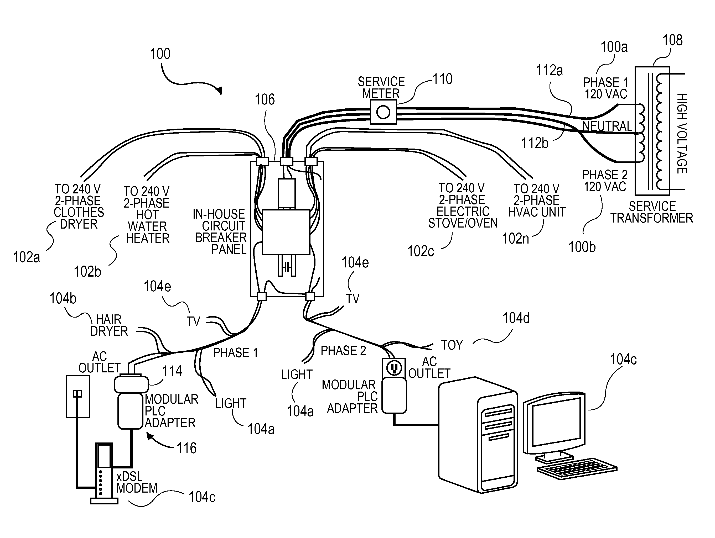
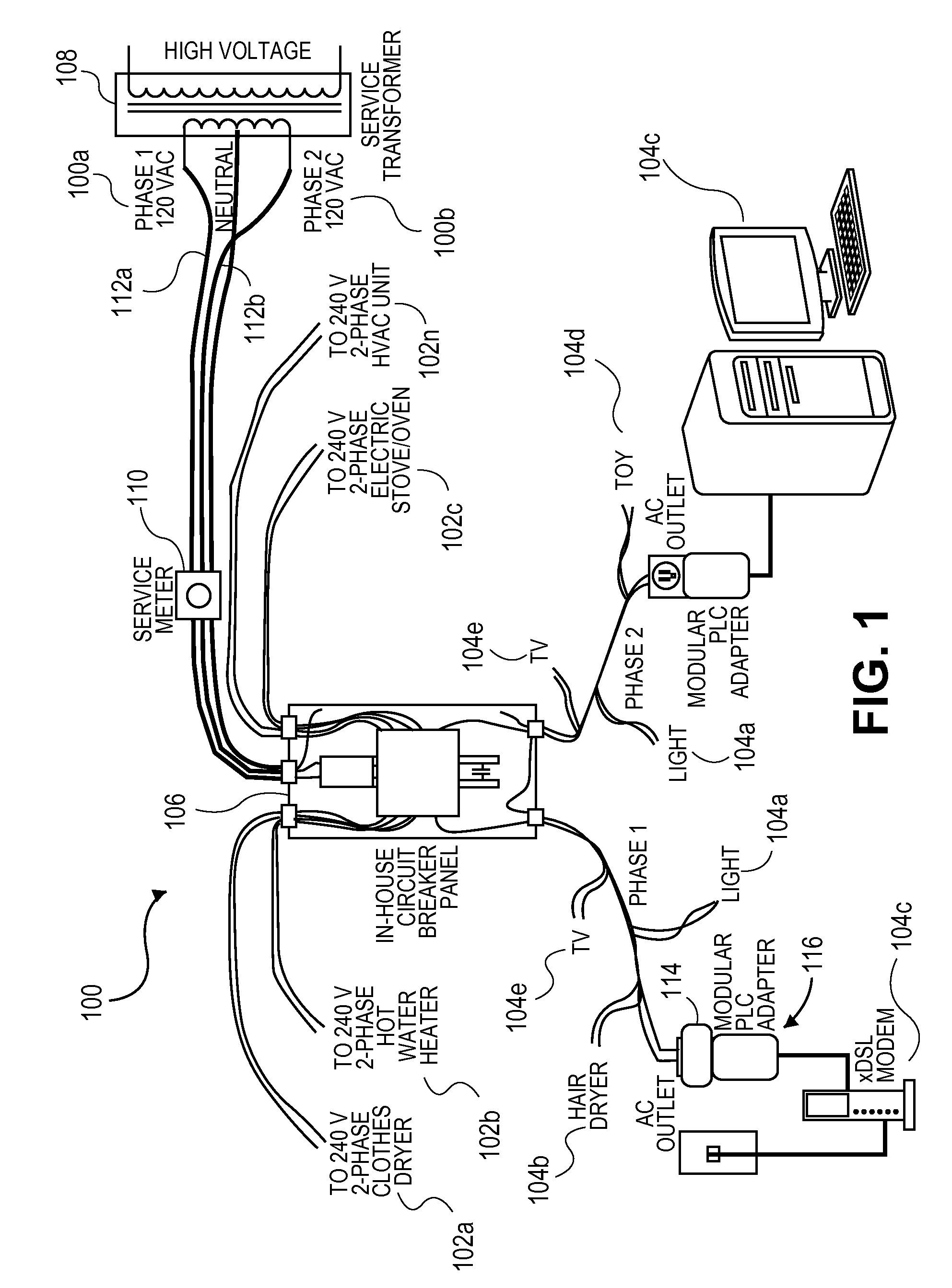
[0033]Determining power usage of a residence, which includes commercial and residential premises, is desirable for a variety of reasons by a variety of parties. For example, consumers who pay for energy usage have a desire to track energy usage between bills to avoid “sticker shock” when receiving a power bill from an energy service provider. Consumers who want additional fire prevention services may find the principles of the present inventive concept desirable. Consumers who desire to know if an appliance is becoming inefficient may also have an interest. In addition, service providers that desire to have additional communications with consum...


PUM


Abstract

A system and method to measure power usage within a residence having a plurality of electrical circuits electrically connected to an over-current protection device may include measuring, by a power measurement device electrically connected to one of the electrical circuits by which power loads draw power, an electrical parameter of the electrical circuits. The electrical parameter may be modeled as a lumped complex impedance. Alternatively, the electrical parameter may be a complex impedance of individual appliances. The measurement may be of AC voltages that may be utilized to calculate complex impedance. Alternatively, the measurement may be made using a reflectometer technique used to compute complex impedance. A data value representative of power being drawn by the power loads connected to the electrical circuits using the measured electrical parameter may be computed. An indicia representative of the computed data value representative of the power being drawn on the electrical circuits may be displayed.

Description

CROSS-REFERENCE TO RELATED APPLICATIONS[0001]This patent application claims priority to U.S. Provisional Patent Application Ser. No. 61 / 244,114 filed Sep. 21, 2009, U.S. Provisional Patent Application Ser. No. 61 / 264,162 filed Nov. 24, 2009, and U.S. Provisional Patent Application Ser. No. 61 / 357,412 filed Jun. 22, 2010; the entire contents of which are herein incorporated by reference in their entireties.BACKGROUND OF THE INVENTION[0002]Power usage in homes, offices, and other building structures (residences) are generally used throughout a billing period without a consumer or customer knowing how much the power usage bill will be until a bill from a power company is delivered to the consumer. In many cases, the power or electric bill causes the consumer “sticker shock” due to the power usage being more than anticipated. As consumers and businesses have more electronic devices these days (e.g., large screen televisions, computers, etc.), power usage bills have generally increased o...

Claims


Application Information

Patent Timeline
Patent Type & Authority Applications(United States)
IPC IPC(8): G06F1/28G06Q30/00
CPCG06Q30/02G06Q50/06G06Q30/0259G06Q30/0251
Inventor MAMMONE, RICHARD JAMES
Owner RUTGERS THE STATE UNIV
Why Eureka
Try Eureka