
Optical Detection of Interrupted Fluid Flow to Ablation Probe

a technology of optical detection and fluid flow, applied in the field of optical detection of interrupted fluid flow to an ablation probe, can solve the problems of rapid failure of microwave ablation devices and susceptible to rapid failure of ablation probes

Active Publication Date: 2011-03-24
TYCO HEALTHCARE GRP LP
View PDF69 Cites 125 Cited by
  • Summary
  • Abstract
  • Description
  • Claims
  • Application Information

AI Technical Summary

Problems solved by technology

During operation of a microwave ablation device, if proper cooling is not maintained, e.g., flow of coolant or buffering fluid is interrupted, the microwave ablation device may exhibit rapid failures due to the heat generated from the increased reflected power.
When a bubble filled with even a small volume of air or multiple air bubbles in close proximity to each other are introduced into an ablation probe, e.g., when the ablation probe is operating at a high power level, the ablation probe may be susceptible to rapid failure due to overheating conditions.

Method used


Image

  • Optical Detection of Interrupted Fluid Flow to Ablation Probe
  • Optical Detection of Interrupted Fluid Flow to Ablation Probe
  • Optical Detection of Interrupted Fluid Flow to Ablation Probe

Examples


Embodiment Construction

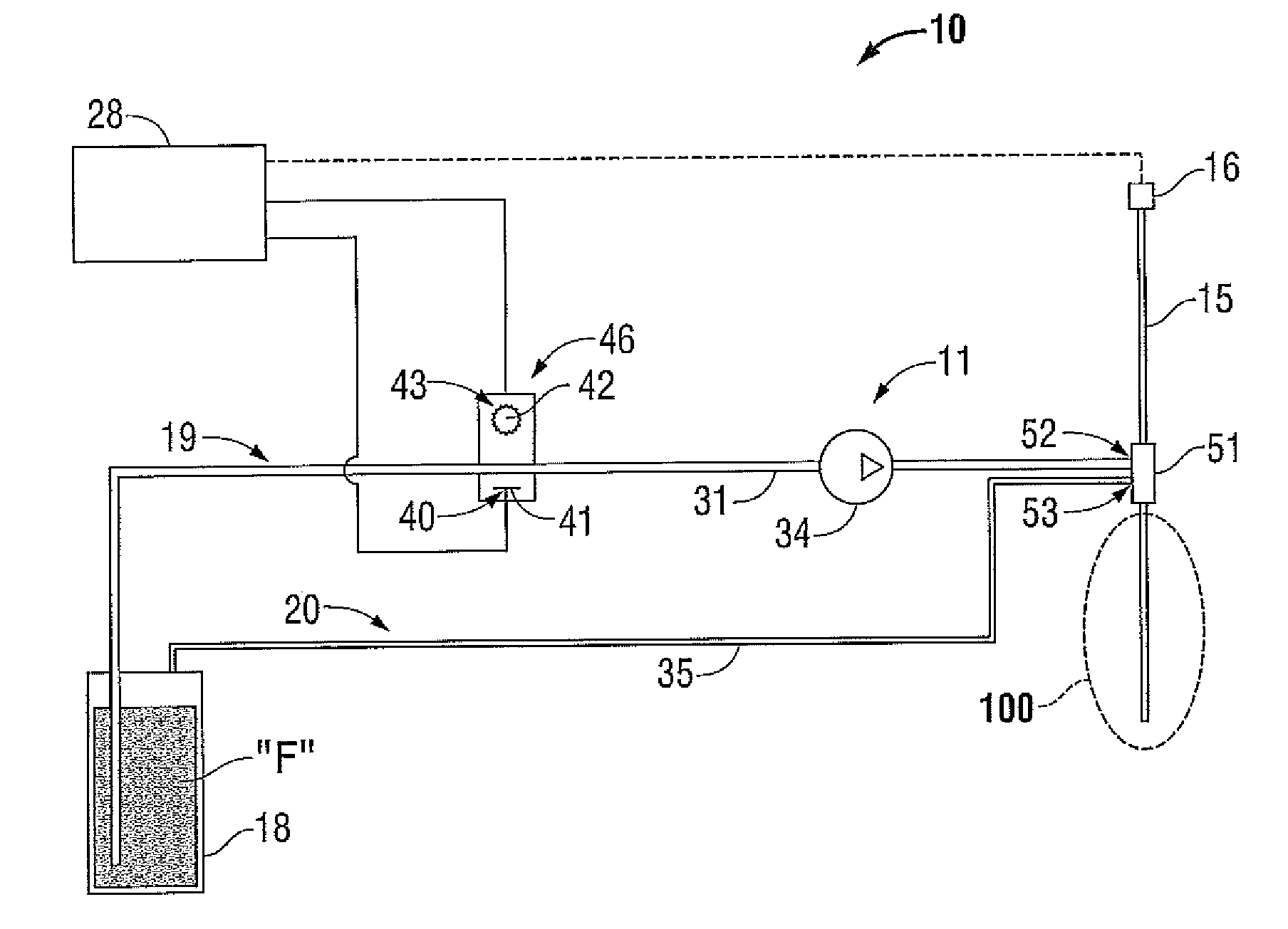
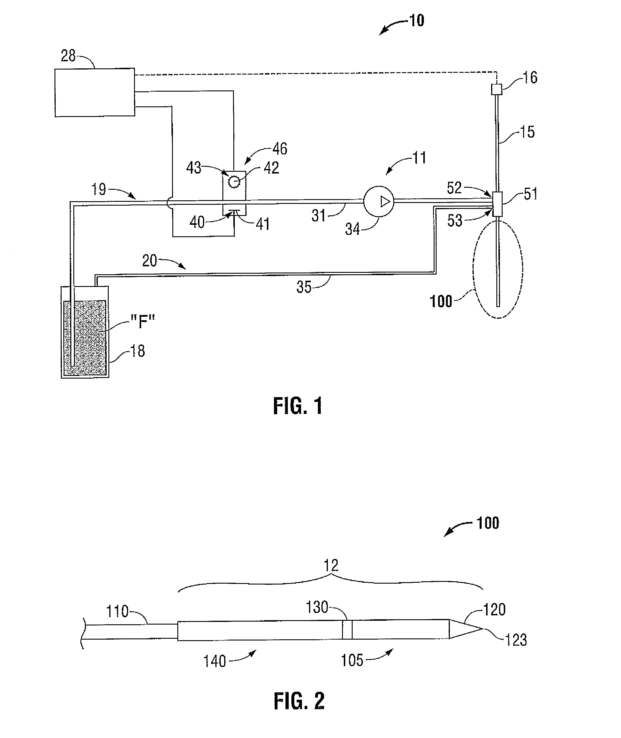
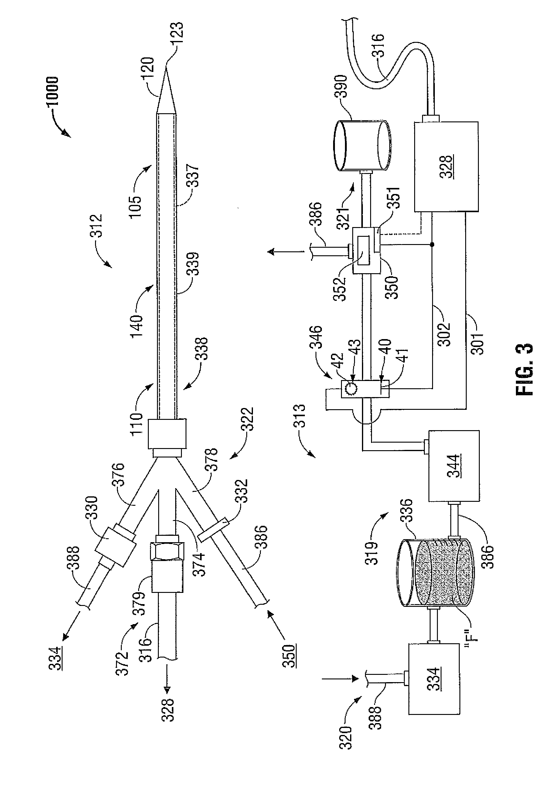
[0021]Hereinafter, embodiments of the presently disclosed systems and methods for optical detection of interrupted fluid flow to an electrosurgical device are described with reference to the accompanying drawings. Like reference numerals may refer to similar or identical elements throughout the description of the figures. As shown in the drawings and as used in this description, and as is traditional when referring to relative positioning on an object, the term “proximal” refers to that portion of the apparatus that is closer to the user and the term “distal” refers to that portion of the apparatus that is further from the user.

[0022]Electromagnetic energy is generally classified by increasing energy or decreasing wavelength into radio waves, microwaves, infrared, visible light, ultraviolet, X-rays and gamma-rays. As it is used in this description, “microwave” generally refers to electromagnetic waves in the frequency range of 300 megahertz (MHz) (3×10⁸ cycles / second) to 300 gigaher...


PUM


Abstract

An electrosurgical system includes an electrosurgical device adapted to direct energy to tissue and a fluid path leading to the electrosurgical device. The system also includes an optical sensor unit operably associated with the fluid path. The optical sensor unit includes a light-emitting element to generate light output and a light-receiving element to collect light outputted from the light-emitting element. The light-emitting element and the light-receiving element are disposed such that light output from the light-emitting element passes through the fluid path to the light-receiving element. The optical sensor unit is capable of detecting an air bubble in the fluid path passing through the optical sensor unit using a sensed characteristic of light collected at the light-receiving element.

Description

BACKGROUND[0001]1. Technical Field[0002]The present disclosure relates to detection devices for use in electrosurgical devices and, more particularly, to systems and methods for optical detection of interrupted fluid flow to an ablation probe.[0003]2. Discussion of Related Art[0004]Treatment of certain diseases requires the destruction of malignant tissue growths, e.g., tumors. Electromagnetic radiation can be used to heat and destroy tumor cells. Treatment may involve inserting ablation probes into tissues where cancerous tumors have been identified. Once the probes are positioned, electromagnetic energy is passed through the probes into surrounding tissue.[0005]In the treatment of diseases such as cancer, certain types of tumor cells have been found to denature at elevated temperatures that are slightly lower than temperatures normally injurious to healthy cells. Known treatment methods, such as hyperthermia therapy, heat diseased cells to temperatures above 41° C. while maintaini...

Claims


Application Information

Patent Timeline
Patent Type & Authority Applications(United States)
IPC IPC(8): A61N1/00
CPCA61B18/1206A61B18/1815A61B2018/00011A61B18/1233
Inventor WILLYARD, RICHARD A.BRANNAN, JOSEPH D.
Owner TYCO HEALTHCARE GRP LP
Learn More