Low-power voltage regulator

a voltage regulator and low-power technology, applied in the direction of electric variable regulation, process and machine control, instruments, etc., can solve the problems of poor analog performance and high turn-on voltage, and achieve the effect of reducing power dissipation and circuit area

Inactive Publication Date: 2011-03-03
SILICON LAB INC
View PDF10 Cites 15 Cited by
  • Summary
  • Abstract
  • Description
  • Claims
  • Application Information

AI Technical Summary

Problems solved by technology

However, such high-voltage devices generally occupy a large area, have a high turn-on voltage, and have poor analog performance (e.g., poor device matching and large parasitic capacitance) as compared to low-voltage device counterparts.

Method used


Image

  • Low-power voltage regulator
  • Low-power voltage regulator
  • Low-power voltage regulator

Examples


Embodiment Construction

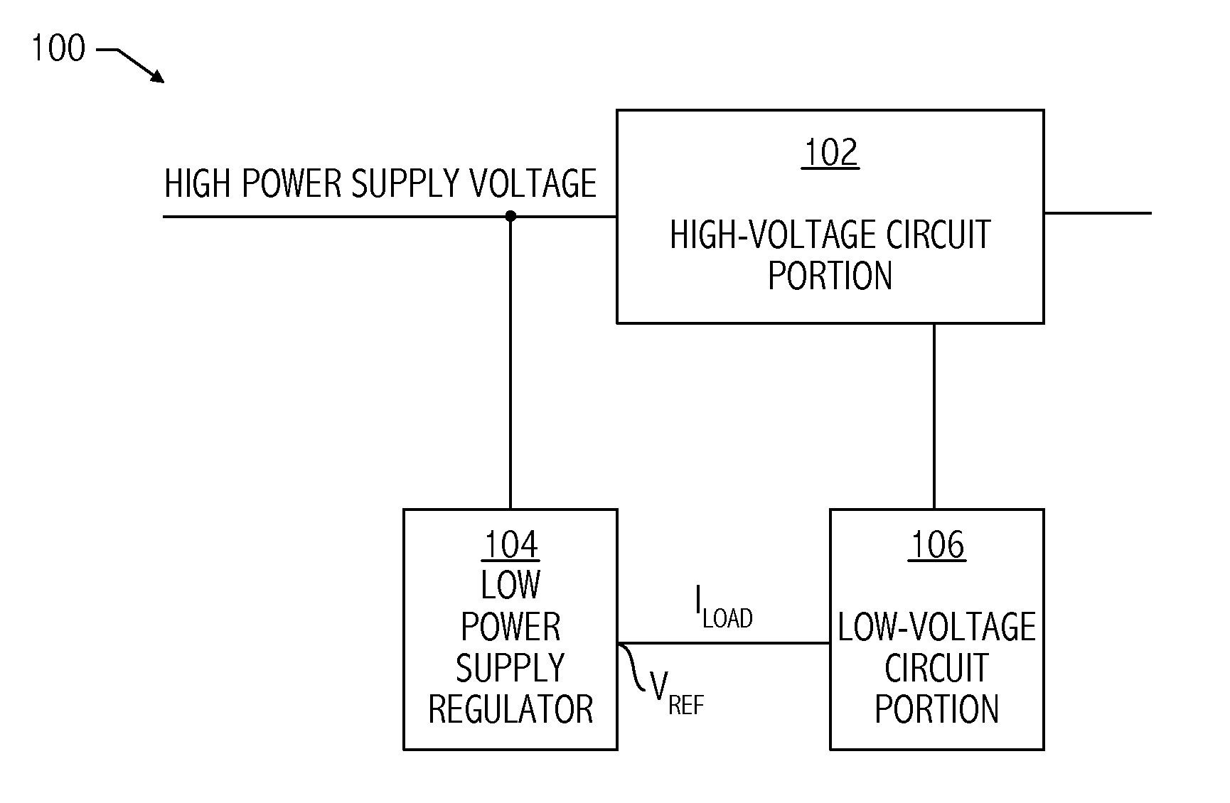
[0020]Referring to FIG. 1, an integrated circuit implementation of a high power supply voltage application (e.g., integrated circuit portion 100) includes a high-voltage circuit portion (e.g., circuit portion 102) and a local, low-voltage circuit portion (e.g., circuit portion 106). Circuit portion 102 includes circuits that operate at high voltage levels, e.g., driver circuits. Low-voltage circuit portion 106 includes local circuitry that implements functions that need not operate at high voltage levels. Low power supply regulator circuit 104 is configured to generate a low-voltage, local power supply for low-voltage circuit portion 106. Integrated circuit portion 100 may include a driver circuit, an isolator circuit, combinations thereof, or other suitable circuits. Exemplary isolator circuits are described in U.S. patent application Ser. No. 12 / 129,039, filed May 29, 2008, entitled “ISOLATOR CIRCUIT INCLUDING A VOLTAGE REGULATOR,” naming Donald E. Alfano, Timothy J. Dupuis, Zhiwe...


PUM


Abstract

A technique for reducing power dissipation and circuit area for a high voltage application includes creating a low-voltage, local power supply for use with local circuitry. In at least one embodiment of the invention, an apparatus includes an output node configured to provide a regulated output voltage. The apparatus includes a variable current source coupled to a first power supply node, wherein the variable current source is configured to provide an output current to the output node based on a control signal on a control node. The apparatus includes a feedback circuit configured to generate the control signal based on a mirrored current. The mirrored current is a mirrored version of a residual current flowing between the output node and a second power supply node. The regulated output voltage has a voltage level less than the voltage level on the first power supply node.

Description

BACKGROUND[0001]1. Field of the Invention[0002]This invention relates to integrated circuits and more particularly to voltage regulation on integrated circuits.[0003]2. Description of the Related Art[0004]In some integrated circuit applications, such as power conversion applications and driver applications, high-voltage devices are necessary to withstand high power supply voltage levels (e.g., approximately 24V or approximately 32V). In general, a high-voltage device includes a gate oxide layer that is thicker than the gate oxide layer of low-voltage device counterparts. Accordingly, a high-voltage device has a threshold voltage (Vt) magnitude greater than the magnitude of Vt(|Vt|) of a low-voltage device and has a gate oxide breakdown voltage greater than the gate oxide breakdown voltage of a low-voltage device. However, such high-voltage devices generally occupy a large area, have a high turn-on voltage, and have poor analog performance (e.g., poor device matching and large parasi...

Claims


Application Information

Patent Timeline
Patent Type & Authority Applications(United States)
IPC IPC(8): G05F3/16
CPCG05F3/242G05F1/607
Inventor DONG, ZHIWEITANG, WILLIAM W. K.THOMSEN, AXEL
Owner SILICON LAB INC
Why Eureka
Try Eureka