Temperature sensor and method for adjusting such a temperature sensor

a temperature sensor and temperature sensor technology, applied in the field of temperature sensors, can solve problems such as inability to solve in a very simple manner, and achieve the effect of improving adjustability and switching accuracy

Active Publication Date: 2011-02-24
E G O ELEKTRO GERAETEBAU GMBH
View PDF29 Cites 2 Cited by
  • Summary
  • Abstract
  • Description
  • Claims
  • Application Information

AI Technical Summary

Benefits of technology

[0008]Unlike in the prior art, this arrangement makes it possible to change the position of the second switching spring base in the housing of the temperature sensor itself, rather than changing the position of a switching spring, that is to say the second switching spring, with respect to its second switching spring base, to which it is fastened, as a relative movement. This considerably improves the adjustability and the switching accuracy. In particular, the second switching spring base can be permanently locked or fixed to the housing of the temperature sensor in a stable manner in this case, for example by firmly welding the metal switching spring base to a metal part in the temperature sensor housing. Subsequent changes or undesirable adjustments can thus be prevented.
[0009]In another embodiment of the invention, the rod rests against the first switching spring in the manner mentioned by means of the said intermediate element in order to trigger said spring at the triggering point or at its switching point. Such an intermediate element has the advantage that it may be designed in an elongated and rod-like manner and, through the switching spring, can thus also constitute the bearing point for the second switching spring.

Problems solved by technology

The setting of these triggering points or switching temperatures is very important and technically cannot be solved in a very simple manner.

Method used


Image

  • Temperature sensor and method for adjusting such a temperature sensor
  • Temperature sensor and method for adjusting such a temperature sensor

Examples


Embodiment Construction

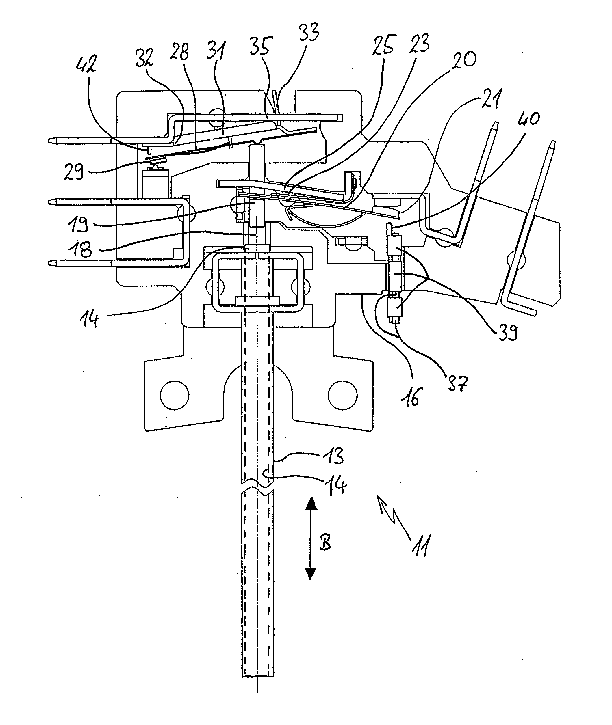
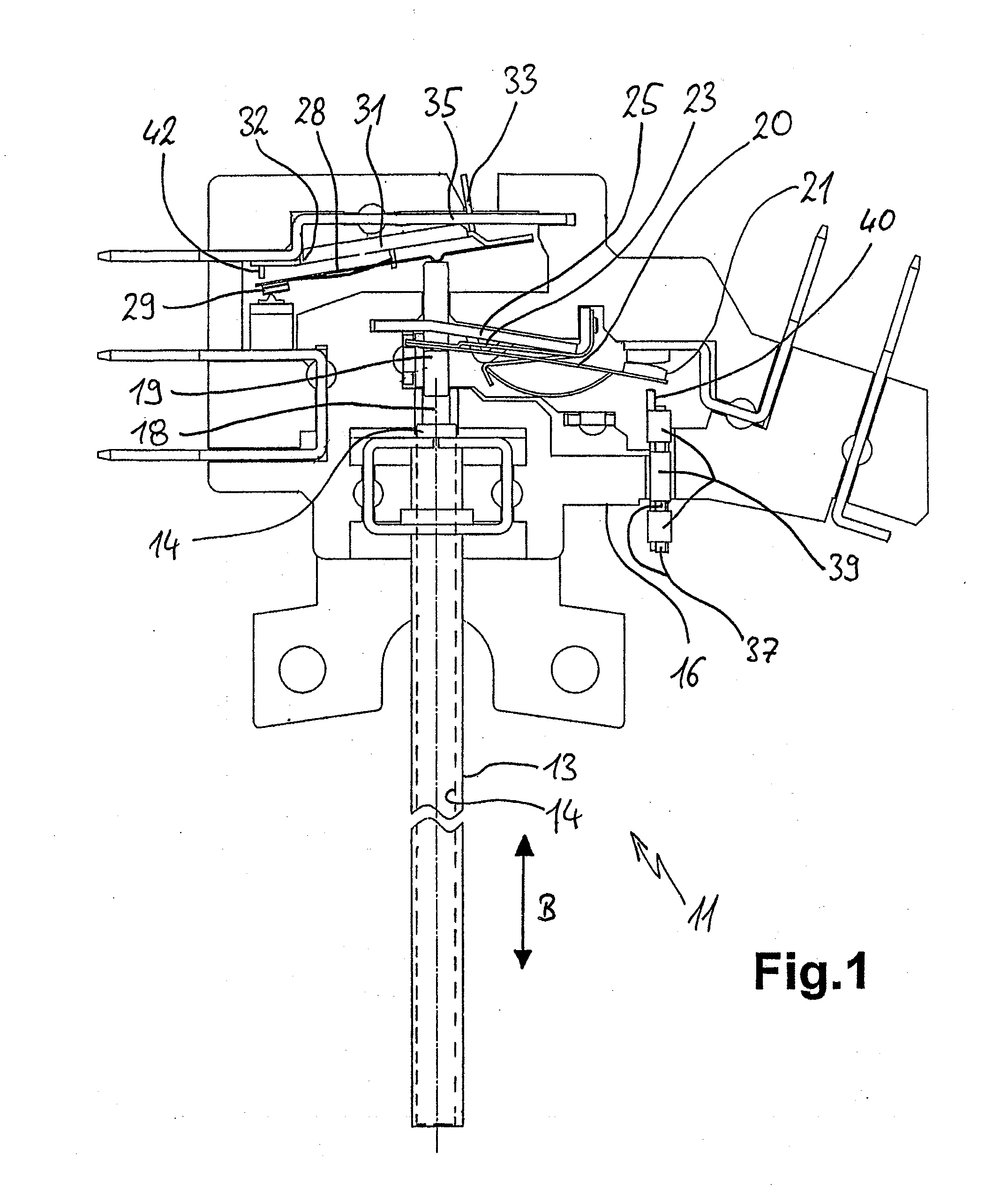
[0022]FIG. 1 shows a sectional plan view of a temperature sensor 11 according to the invention with an elongated sensor part which consists, in a known manner, of a tube 13, usually a metal tube, and an elongated rod 14, usually a ceramic rod, contained in said tube. In the case of temperature fluctuations, the tube 13 and the rod 14 undergo different linear expansions in their longitudinal direction, thus resulting in a relative movement in the direction of movement B. Since the lower end of the rod 14 is either pressed into the tube 13 with a spring force acting from above or is even fixed, for example clamped, in said tube, a longitudinal movement results at the upper end of the two parts. The tube 13 is fastened to a housing 16 of the temperature sensor 11 in a manner known per se, the housing 16 consisting of an insulating material, advantageously ceramic material. The rod 14 protrudes somewhat from the top of the tube 13 and rests against an intermediate pin 18 which is known ...


PUM


Abstract

A temperature sensor for a radiant heater has a first tubular expansion element which is connected to its housing and contains a second rod-like expansion element, the two expansion elements having different coefficients of thermal expansion. The temperature sensor has two switching springs for different switching points. In order to adjust a second switching spring, which is fastened to a second switching spring base, the second switching spring base can be moved in the longitudinal direction of the rod and is then permanently fixed by bending or welding.

Description

CROSS REFERENCE TO RELATED APPLICATIONS[0001]This application claims priority to German Application Number 10 2009 038 960.1 filed on Aug. 19, 2009, the contents of which are incorporated by reference for all that it teaches.FIELD OF THE INVENTION[0002]The invention relates to a temperature sensor, in particular to a so-called “rod thermostat,” and to a method for adjusting such a temperature sensor.BACKGROUND OF THE INVENTION[0003]U.S. Pat. No. 7,345,572 discloses a temperature sensor, which is also referred to as a rod thermostat. It contains two switching springs which are triggered by a second expansion element which is mounted in a tubular first expansion element. The first expansion element usually consists of a metal tube, whereas the second expansion element is a ceramic rod. As a result of different coefficients of thermal expansion, essentially only the tube expands during heating and the rod moves, relative to the latter, out of a housing of the temperature sensor, which ...

Claims


Application Information

Patent Timeline
Patent Type & Authority Applications(United States)
IPC IPC(8): H01H37/48
CPCH01H37/22H01H37/48H01H37/26
Inventor CASTILLO, PHILIPP PEREZREICHERT, WILLISCHLENKER, BRUNO
Owner E G O ELEKTRO GERAETEBAU GMBH
Why Eureka
Try Eureka