
Wind turbine generator

a wind turbine generator and wind turbine technology, applied in the direction of electric generator control, machines/engines, sliding contact bearings, etc., can solve the problems of difficult to reduce the number of components to achieve weight reduction, and achieve the effect of reducing the number of components, reducing weight, and effective use of the flang

Active Publication Date: 2011-02-10
MITSUBISHI HEAVY IND LTD
View PDF11 Cites 14 Cited by
  • Summary
  • Abstract
  • Description
  • Claims
  • Application Information

AI Technical Summary

Benefits of technology

[0012]The above-described configuration of the related art adopts the slide bearing that functions as the yaw slew ring that also functions as a yaw brake between the tower and the nacelle. Accordingly, the tower, the yaw slew ring (bearing) structure, and the nacelle are individually configured as separate structures, which makes it difficult to reduce the number of components to achieve weight reduction.
[0013]Against such a backdrop, it is desired to reduce the number of components that constitute the yaw system and the weight thereof.
[0014]The present invention is made in consideration of the above-described circumstances, and it is an object thereof to provide a wind turbine generator in which the number of components and weight of the yaw system mounted atop the tower can be reduced.
[0018]With such a wind turbine generator, the yaw slew ring is a slide bearing fixed to the lower surface of the nacelle with a substantially L-shaped-cross-section bracket; and the slide bearing is configured to slidably support a flange formed at the upper end of the tower with slide pads held by the bracket. Therefore, the slide bearing can be configured by effectively using the flange. Thus, the slide bearing serves as the yaw slew ring that also has the function of the yaw brake.
[0019]In the above-described invention, it is preferable that the bracket be divided into a plurality of portions in the circumferential direction. This makes it easy to mount the bracket on the upper end of the tower.
[0021]According to the above-described present invention, since the slide bearing is configured by effectively using the flange formed at the upper end of the tower, weight reduction can be achieved by reducing the number of components of the slide bearing itself. Furthermore, since the slide bearing functions as the yaw slew ring that serves also as the yaw brake, a wind turbine generator can be provided in which the number of components can be reduced also for the entire yaw system that is mounted atop the tower and that rotates the nacelle, thus allowing weight reduction.

Problems solved by technology

Accordingly, the tower, the yaw slew ring (bearing) structure, and the nacelle are individually configured as separate structures, which makes it difficult to reduce the number of components to achieve weight reduction.

Method used


Image

  • Wind turbine generator
  • Wind turbine generator
  • Wind turbine generator

Examples


Embodiment Construction

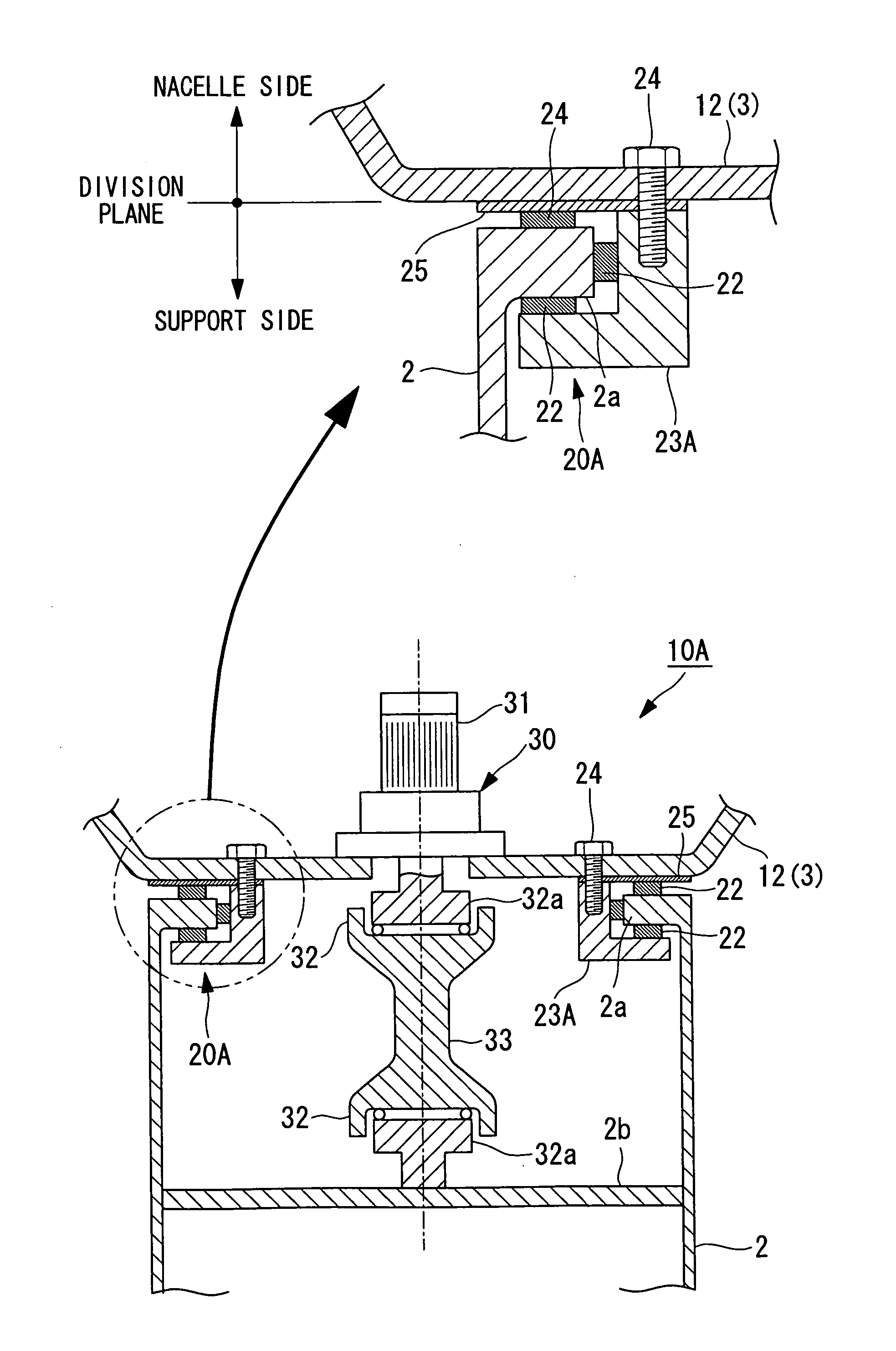
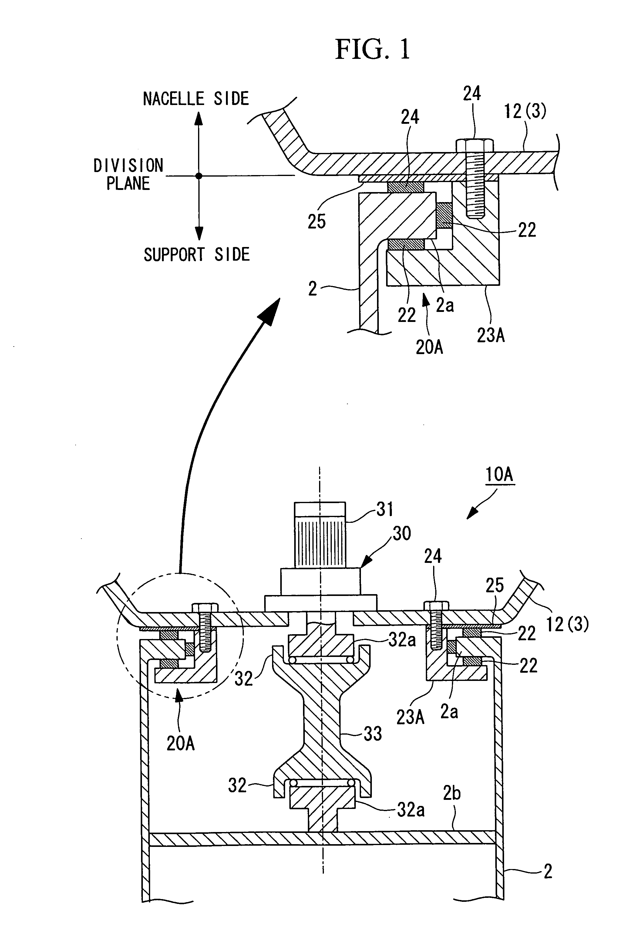
[0036]An embodiment of a wind turbine generator according to the present invention will be described hereinbelow with reference to FIG. 1 and FIG. 2.

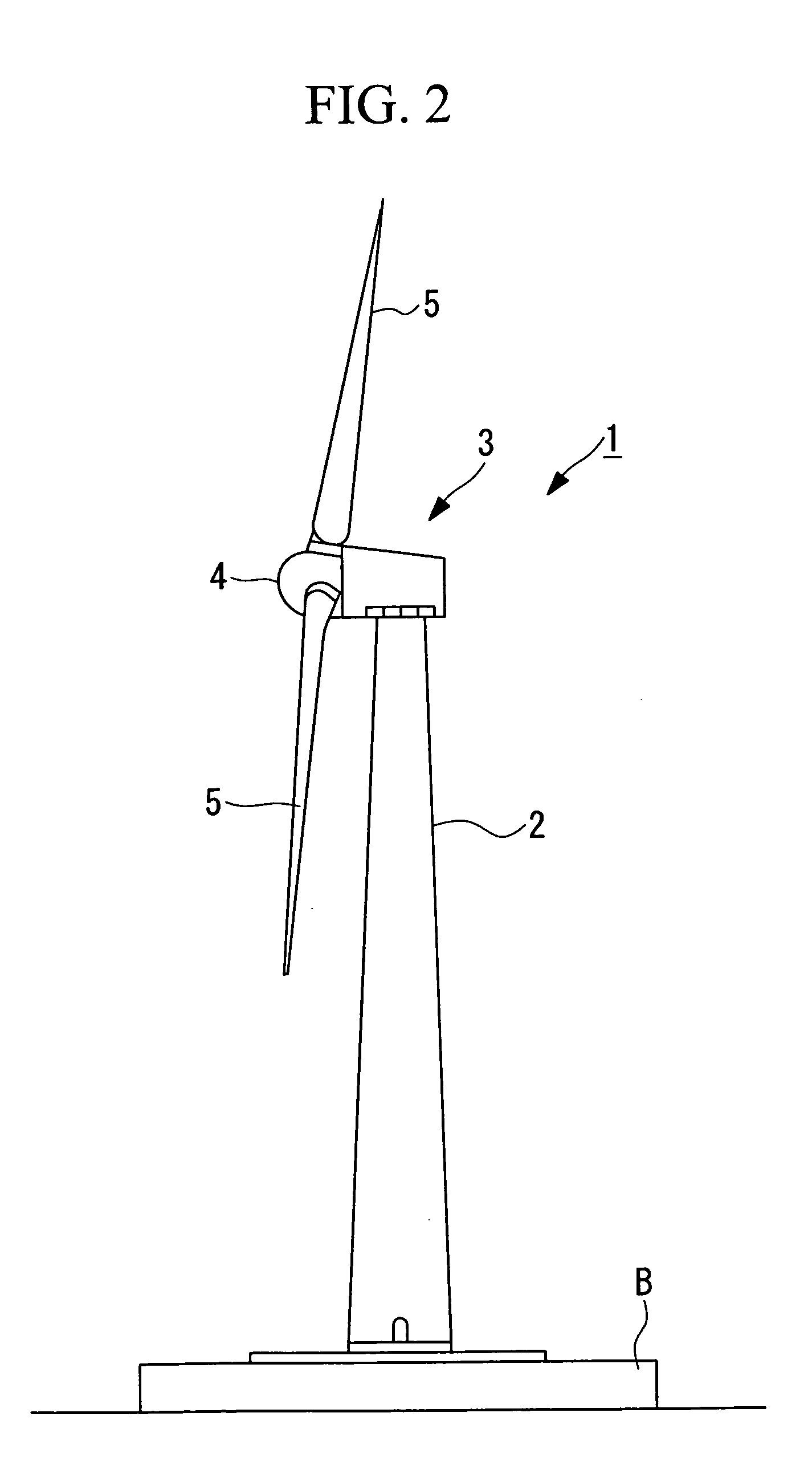
[0037]A wind turbine generator 1 shown in FIG. 2 includes a tower (also referred to as “tower”) 2 vertically erected on a base B, a nacelle 3 mounted at the upper end of the tower 2, and a rotor head 4 provided at the nacelle 3 so as to be rotatable about the substantially horizontal axis thereof.

[0038]The rotor head 4 has a plurality of (for example, three) wind turbine blades 5 mounted radially about its rotation axis. Thus, the power of wind blowing against the wind turbine blades 5 from the direction of the rotation axis of the rotor head 4 is converted to motive power that rotates the rotor head 4 about the rotation axis.

[0039]The above-described wind turbine generator 1 is equipped with a yaw system that rotates the nacelle 3 located at the upper end of the tower 2. This yaw system is a system for pointing the nacelle 3 in an opti...


PUM


Abstract

A wind-driven generator whose yaw system (10A) installed at the upper part of a support (2) is reduced in the number of its components and weight. The wind-driven generator has the yaw system (10A) equipped with a yaw driving device (30), a yaw slewing ring, and a yaw brake and slewing a nacelle installed at the upper part of the support (2) according to the direction of the wind. A yaw slewing ring fixed to a nacelle table plate (12) through a bracket (23A) having a nearly L-shaped cross section functions as the slide bearing (20A). Thus, the slide bearing (20A) slidably supports a flange part (2a) formed at the upper end of the support (2) with slide pads (22) held by the bracket (23A).

Description

TECHNICAL FIELD[0001]The present invention relates to a wind turbine generator equipped with a yaw system that rotates a nacelle (wind-turbine main body) in accordance with the wind direction.BACKGROUND ART[0002]A conventional wind turbine generator that generates electricity by rotating a wind turbine with wind power and transmitting its rotary motion to a generator is provided with a yaw system that rotates (swings) a nacelle in accordance with the wind direction.[0003]The conventional yaw system is constituted of a yaw driving unit, a yaw slew ring, and a yaw brake, whose main components are disposed at the nacelle side. That is, the nacelle fitted with a wind turbine and a powertrain that generates electricity using its rotational power is configured to rotate on the top of a tower by the operation of the yaw system and to generate electricity while pointing in an optimum direction according to the wind direction.[0004]A conventional yaw system 10 shown in FIG. 3 is configured s...

Claims


Application Information

Patent Timeline
Patent Type & Authority Applications(United States)
IPC IPC(8): F03D11/00
CPCF03D7/0204F03D11/0008F05B2260/90Y02E10/723F16C2300/14Y02E10/722F16C17/10F03D80/70F16C2360/31Y02E10/72F05B2240/50
Inventor NUMAJIRI, TOMOHIRO
Owner MITSUBISHI HEAVY IND LTD
Learn More