Wet coating system having annealing chamber

a technology of wet coating and annealing chamber, which is applied in the direction of coatings, liquid surface applicators, electrical devices, etc., can solve the problems of oxidation of thin films and adverse effects on the performance of thin films

Inactive Publication Date: 2011-02-10
HON HAI PRECISION IND CO LTD
View PDF5 Cites 2 Cited by
  • Summary
  • Abstract
  • Description
  • Claims
  • Application Information

AI Technical Summary

Benefits of technology

[0002]This present disclosure relates to wet coating technologies and, particularly, to a wet coating system for forming a thin film on a substrate. The wet coating system is capable of avoiding or at least reducing oxidization of the thin film during the transportation of the substrate film from a coating solution to an annealing chamber.

Problems solved by technology

However, during the transportation of the substrate, the substrate is exposed to the air and therefore the thin film may be oxidized.
This may adversely effect the performance of the thin film.

Method used


Image

  • Wet coating system having annealing chamber
  • Wet coating system having annealing chamber
  • Wet coating system having annealing chamber

Examples


Embodiment Construction

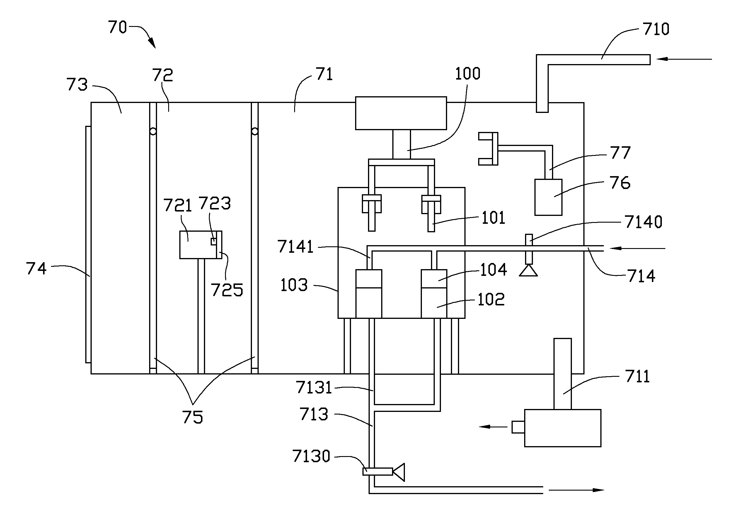
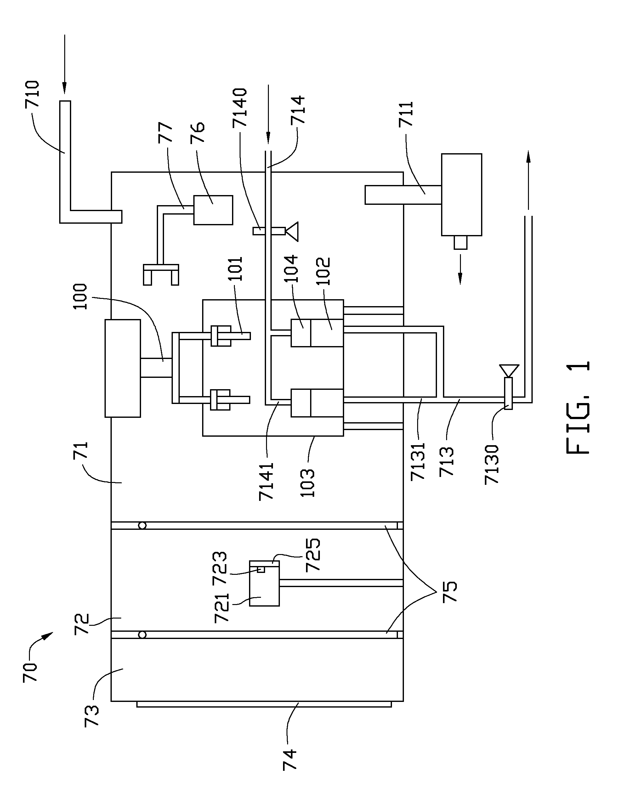
[0014]Referring to FIG. 1, a wet coating system 70, according to an exemplary embodiment, includes a coating chamber 71, an annealing chamber 72, an unloading chamber 73, an access door 74, two automatic doors 75, and a mechanical arm 77.

[0015]The annealing chamber 72 is interposed between the coating chamber 71 and the unloading chamber 73. One of the two automatic doors 75 is interposed between the coating chamber 71 and the annealing chamber 72 and configured for closing an entrance (not labeled) from the coating chamber 71 to the annealing chamber 72. The other automatic door 75 is interposed between the annealing chamber 72 and the unloading chamber 73 and configured for closing an entrance (not labeled) from the annealing chamber 72 to the unloading chamber 73. The access door 74 is disposed on the unloading chamber 73 and configured for closing an entrance (not labeled) from outside to the unloading chamber 73. Before the process of wet coating, a number of substrates 101 are...


PUM

PropertyMeasurementUnit
shapeaaaaaaaaaa
diameteraaaaaaaaaa
inner diameteraaaaaaaaaa

Abstract

An exemplary wet coating system includes a coating chamber, an annealing chamber, an unloading chamber, and a mechanical arm. The coating chamber is configured for allowing a substrate being wet coated therein. The unloading chamber is configured for allowing the substrate being unloaded therein. The annealing chamber is interposed between and communicated with the coating chamber and the unloading chamber and is configured for allowing the substrate being annealed therein. The communicated coating chamber, annealing chamber, and unloading chamber are vacuumized. The mechanical arm is configured for holding the substrate and moving the substrate across the coating chamber, the annealing chamber, and the unloading chamber.

Description

BACKGROUND[0001]1. Technical Field[0002]This present disclosure relates to wet coating technologies and, particularly, to a wet coating system for forming a thin film on a substrate. The wet coating system is capable of avoiding or at least reducing oxidization of the thin film during the transportation of the substrate film from a coating solution to an annealing chamber.[0003]2. Description of Related Art[0004]Generally, a thin film can be formed on a substrate by wet coating. In the process of wet coating, the substrate is firstly dipped into a coating solution and then is transported to an annealing chamber. In the annealing chamber, the substrate is annealed so that the thin film can achieve certain performances. However, during the transportation of the substrate, the substrate is exposed to the air and therefore the thin film may be oxidized. This may adversely effect the performance of the thin film.[0005]Therefore, it is desirable to provide a wet coating system, which can ...

Claims


Application Information

Patent Timeline
Patent Type & Authority Applications(United States)
IPC IPC(8): B05C9/14B05C11/00B05C9/08
CPCB05C3/10H01L21/6715H01L21/67751H01L21/67742H01L21/67173
Inventor HUANG, CHIEN-HAOPEI, SHAO-KAI
Owner HON HAI PRECISION IND CO LTD
Why Eureka
Try Eureka