Harmonic Damper

a technology of damper and handle, applied in the field of dampers, can solve the problems of vibrations passing through the handle or control device, vibrations that may be particularly uncomfortable for operators and passengers, and vibrations that may be generated or subject to various vibrations and resonances

Inactive Publication Date: 2011-01-27
MCPHERSON MATHEW A
View PDF18 Cites 6 Cited by
  • Summary
  • Abstract
  • Description
  • Claims
  • Application Information

AI Technical Summary

Problems solved by technology

Vehicles and other devices may generate or be subject to various vibrations and resonances which may be present throughout the structure of the object.
Vibrations may be uncomfortable and / or fatiguing to an operator and passengers.
Vibrations passing through a handle or control device may be particularly uncomfortable as the vibrations may be absorbed by the hands and arms of a person in contact with the handle or control device.

Method used


Image

  • Harmonic Damper
  • Harmonic Damper
  • Harmonic Damper

Examples


Embodiment Construction

[0032]While this invention may be embodied in many different forms, there are described in detail herein specific preferred embodiments of the invention. This description is an exemplification of the principles of the invention and is not intended to limit the invention to the particular embodiments illustrated. For the purposes of this disclosure, like reference numerals in the figures shall refer to like features unless otherwise indicated.

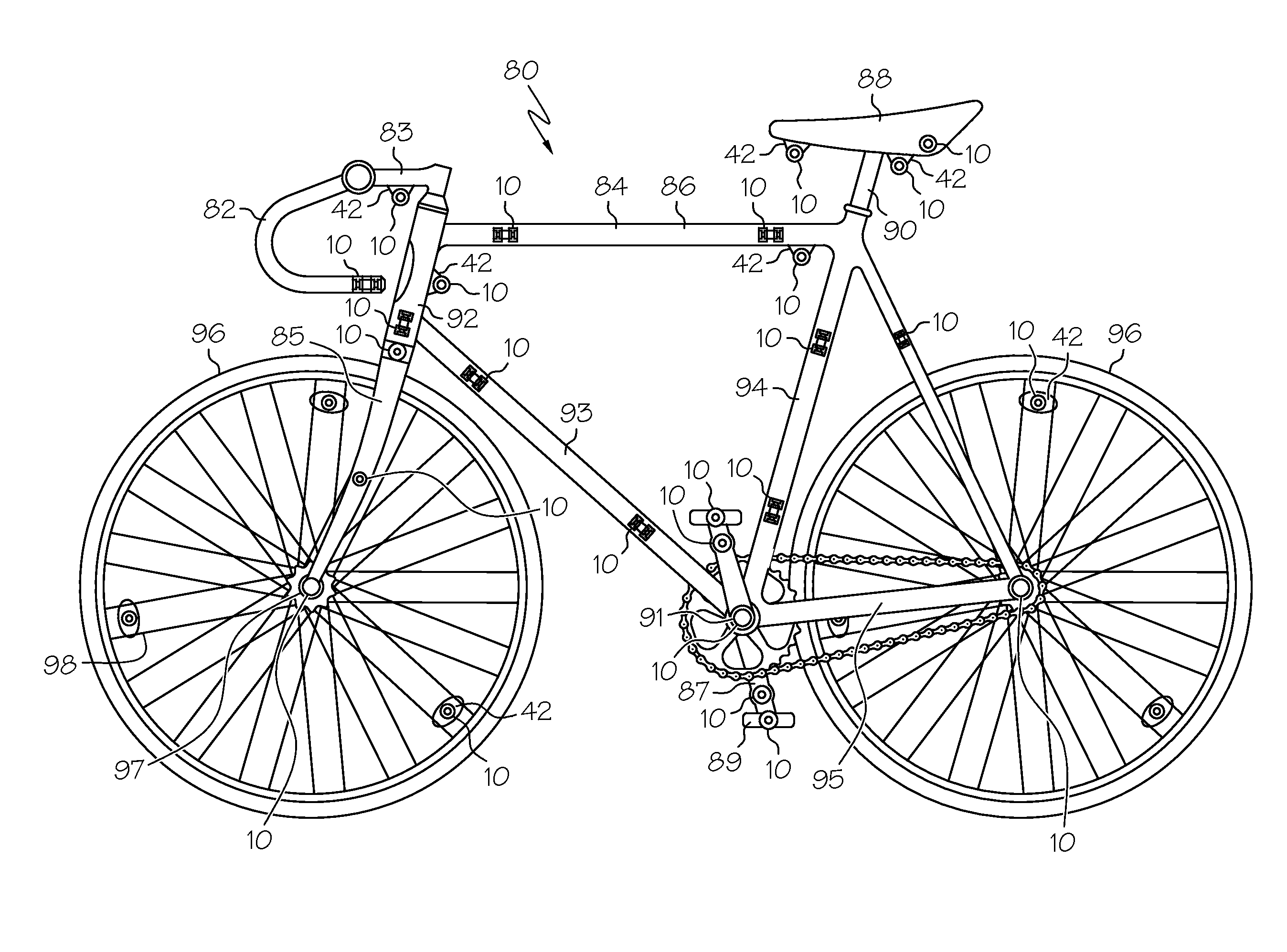
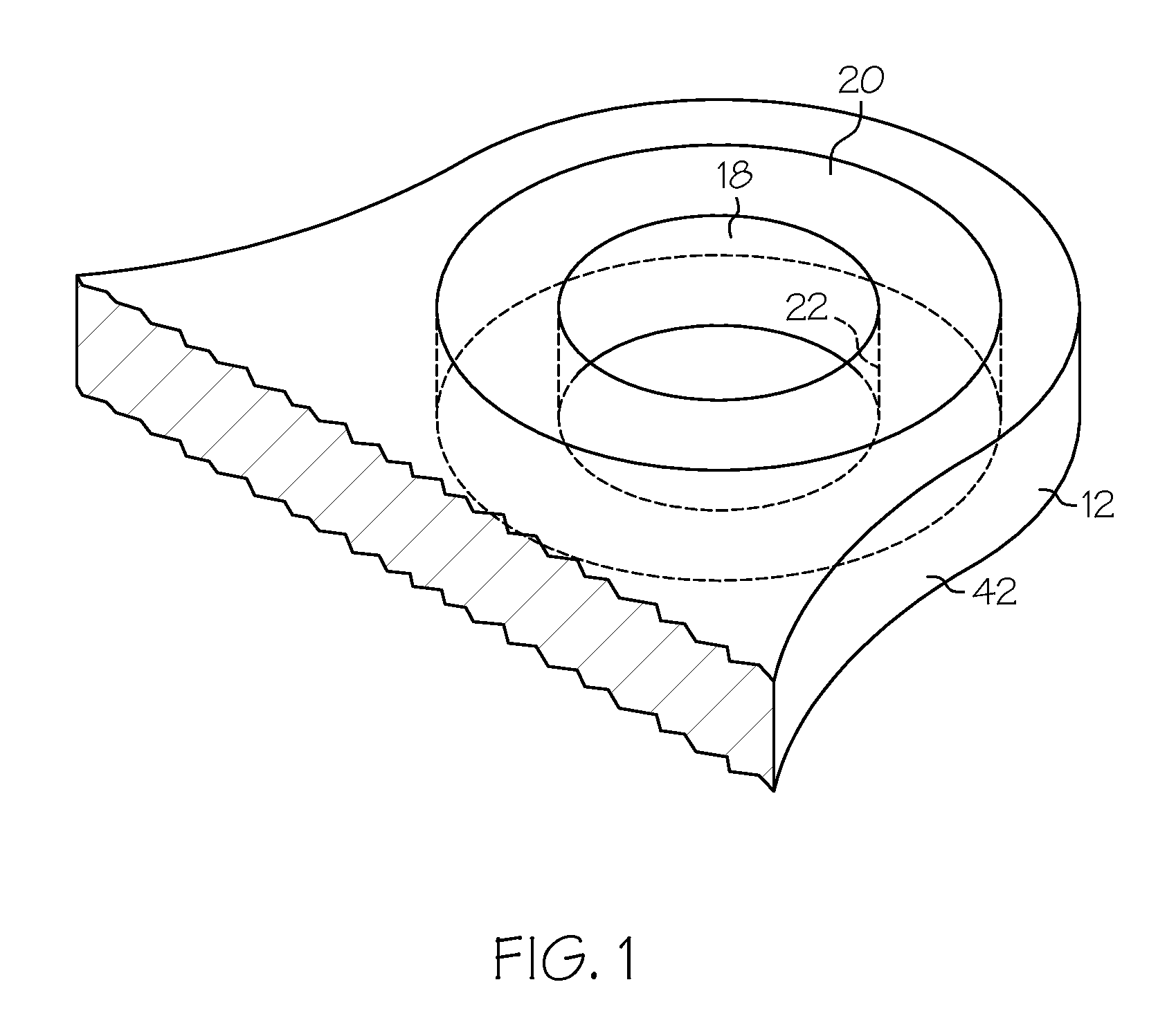
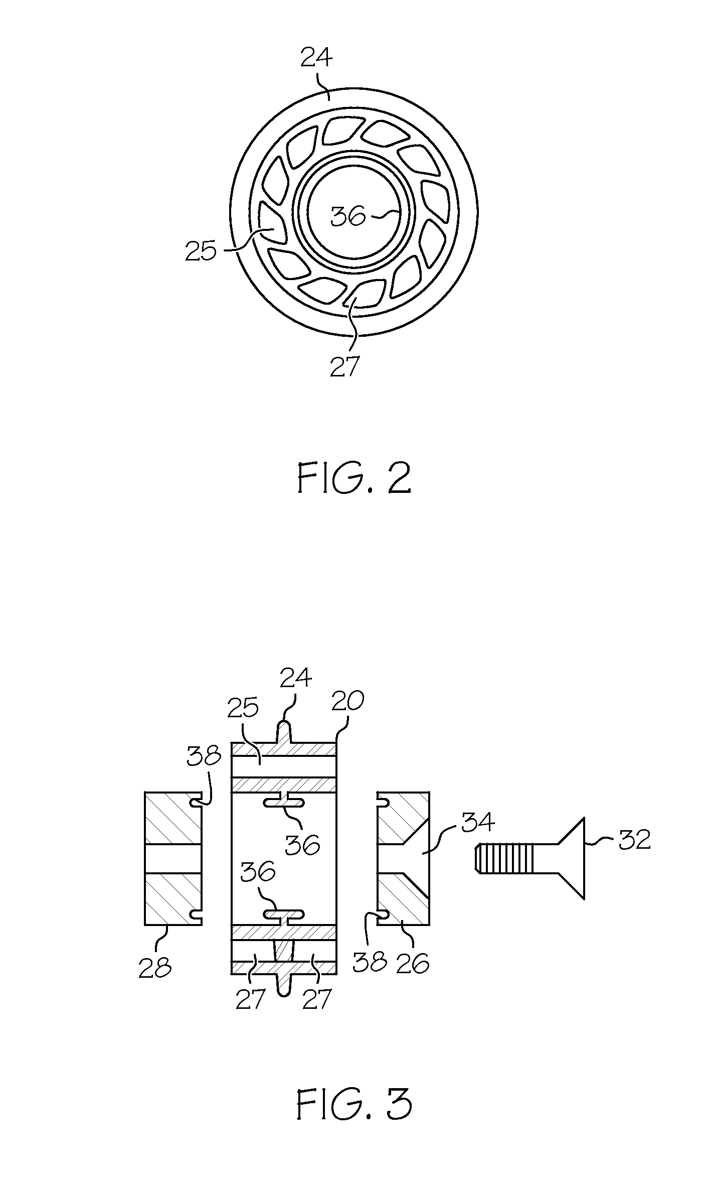
[0033]FIG. 1 shows an embodiment of a damper 10, which may be mounted to any portion of a small vehicle, other transportation device and other rolling and / or motorized device. The damper 10 may reduce vibrations present in the apparatus 12 to which it is mounted. The damper 10 may be installed in a housing or mount 42, which may comprise a portion of the apparatus 12.

[0034]A damper 10 may comprise a weight 18 and a resilient portion or member 20. Desirably, the weight 18 provides a mass that is used by the damper 10 in conjunction with the resil...


PUM


Abstract

A damper for reducing vibrations present in various portions of small vehicles, other transportation devices and other rolling and / or motorized devices, such as bicycles, motorcycles, lawn mowers, snowblowers and the like, may comprise a resilient member and a weight. The resilient member may mounted to a portion of a device having a surface suitable for engaging and retaining the resilient member therein, and the resilient member may have an inside surface suitable for engaging and retaining the weight.

Description

BACKGROUND OF THE INVENTION[0001]This invention relates to a damper which may be used to reduce vibrations in small vehicles, other transportation devices and other rolling and / or motorized devices, such as bicycles, wagons, motorcycles, jet skis, lawn mowers, snowblowers, all-terrain vehicles and the like.[0002]Vehicles are well known and may be used to transport people and various objects, such as cargo. Vehicles generally require an operator, and typically the operator is supported by the vehicle. Other rolling devices, such as lawn mowers and snowblowers, may perform work and may be controlled by an operator.[0003]Vehicles and other devices may generate or be subject to various vibrations and resonances which may be present throughout the structure of the object. Vibrations may pass from the object to the operator, for example through a control device or grip such as a handle, and also through a seat or other support device in cases where the object supports an operator or passe...

Claims


Application Information

Patent Timeline
Patent Type & Authority Applications(United States)
IPC IPC(8): F16F7/10B62K3/02B62K19/00F16F7/108
CPCF16F7/108
Inventor MCPHERSON, MATHEW
Owner MCPHERSON MATHEW A
Why Eureka
Try Eureka