Solar tracker with parabolic concentrator

a solar tracker and concentrator technology, applied in the direction of solar heat collector controllers, solar-ray concentration, solar heat collectors moving/orienting, etc., can solve problems such as unsatisfactory solutions, and achieve the effect of facilitating the constructive formation of assemblies

Inactive Publication Date: 2010-12-30
MECANIZADOS SOLARES
View PDF10 Cites 11 Cited by
  • Summary
  • Abstract
  • Description
  • Claims
  • Application Information

AI Technical Summary

Benefits of technology

[0009]A securing of the mirrors is thus obtained which allows individually regulating the position of each mirror in a vertical direction, in a lateral direction and in a depth direction, for the correct orientation in relation to the focusing towards the convergence point of the parabolic concentrator, the position of the mirrors on the bearing structure being able to be adjusted before incorporating said structure on the mobile assembly in the solar tracker, which facilitates the constructive formation of the assembly.
[0010]The ties supporting the Stirling engine are attached to said engine by means of tensioners which can be regulated in length, which establish pivoting attachments with respect to the engine and with respect to the corresponding tie, such that the position and orientation of the Stirling engine in relation to the parabolic concentrator can be adjusted with precision by means of regulating the tensioners of the different ties.

Problems solved by technology

For the effectiveness of these arrangements, the position of the mirrors of the parabolic concentrator, as well as the placement of the energy-converting element facing said parabolic concentrator is extremely important for which complicated and expensive solutions have been developed, with which, however, the problem is not satisfactorily solved.

Method used


Image

  • Solar tracker with parabolic concentrator
  • Solar tracker with parabolic concentrator
  • Solar tracker with parabolic concentrator

Examples


Embodiment Construction

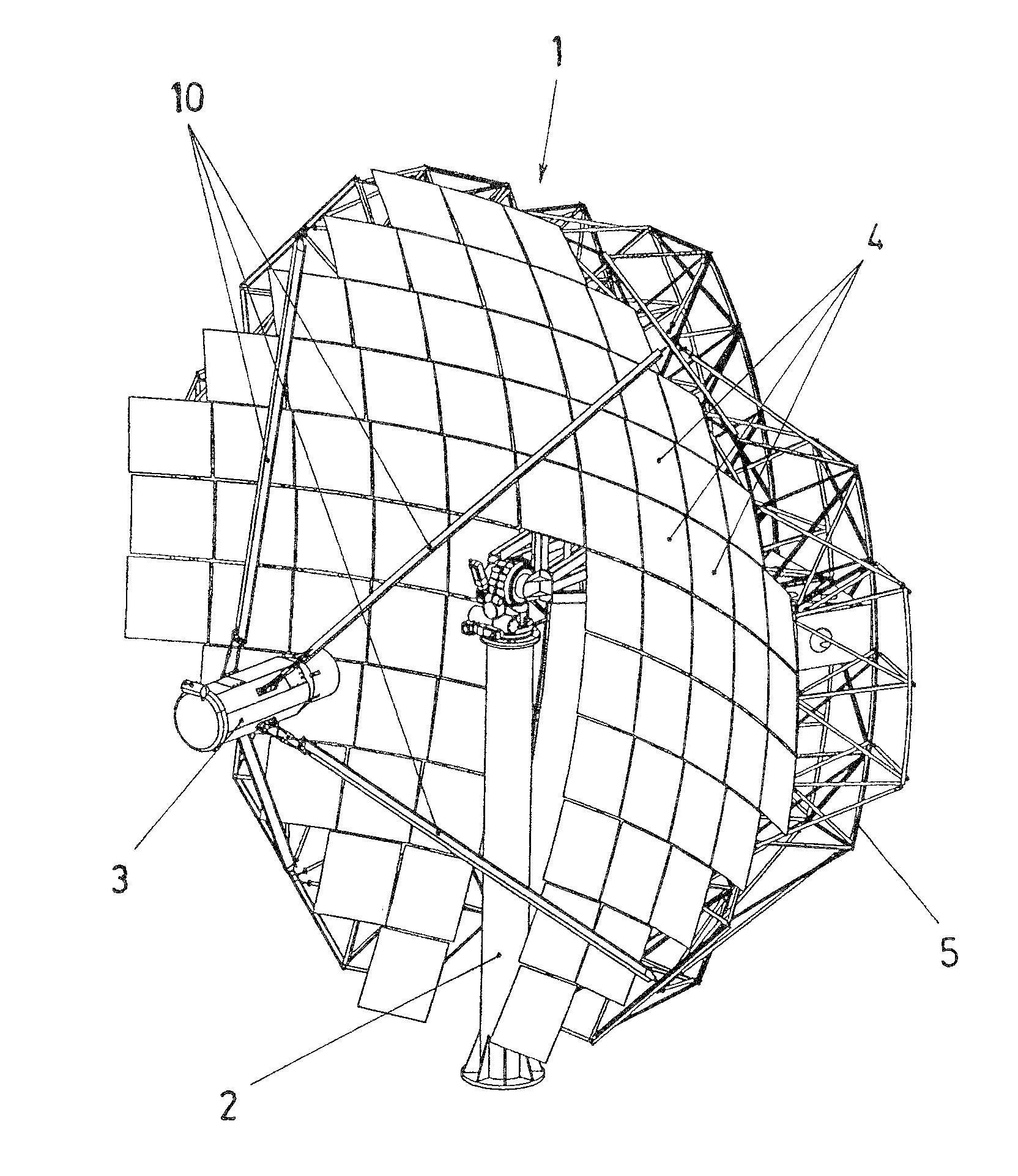
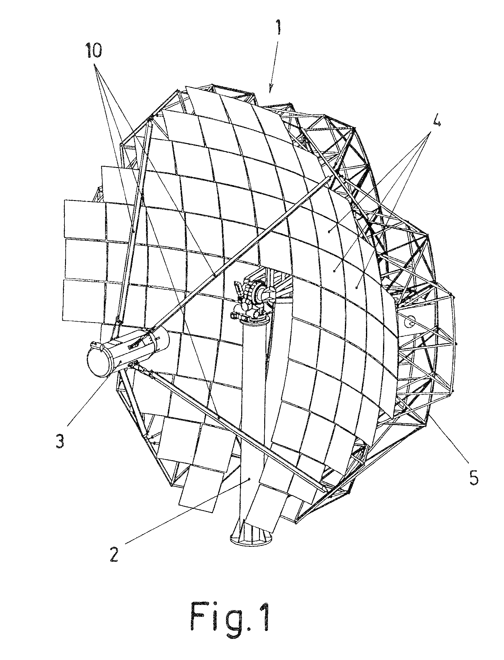
[0021]The object of the invention relates to a solar tracker formed by a parabolic concentrator (1) incorporated in a solar tracking assembly on a supporting column (2), with a Stirling engine (3) located at a focusing point of the projection of said parabolic concentrator (1), which is made up of a distribution of mirrors (4), each of them placed individually in an orientation of reflection towards the Stirling engine (3).

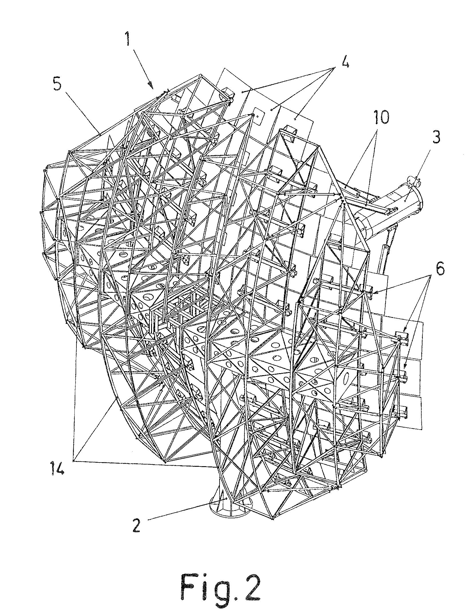
[0022]The mirrors (4) are secured on a bearing structure (5) acting as a structural framework of the parabolic concentrator (1), each mirror (4) being secured individually by means of anchors (6), as observed in FIGS. 2 and 6.

[0023]As observed in FIG. 7, each of said anchors (6) comprises a plate (7) on which the corresponding mirror (4) is secured in the front part, whereas angle bars (8) are attached to said plate (7) at the rear part, which angle bars are secured by means of fasteners screwed through holes (8.1) slit in a vertical direction, which allow a slidi...


PUM


Abstract

The invention relates to a solar tracker with parabolic concentrator, comprising a parabolic concentrator (1) formed by a composition of mirrors (4) focused towards a Stirling engine (3), the mirrors (4) being located on a bearing structure (5), with securing by means of anchors (6) which allow a regulation in a vertical direction, in a lateral direction and in a depth direction, whereas the Stirling engine (3) is secured on the same bearing structure (5) by means of ties (10) which are attached to said Stirling engine (3) by means of two securing elements which can be adjusted in length, the bearing structure (5) being formed by parallel vertical lattices (14) comprising in their formation sheet metal boxes attached to one another by means of other intermediate sheet metal boxes.

Description

FIELD OF THE ART[0001]The present invention relates to the use of solar radiation for generating consumable energy forms, proposing a solar tracker incorporating a parabolic mirror concentrator to project the solar radiation onto a Stirling engine, with structural formation features improving the regulation of the position of the mirrors and of the Stirling engine, as well as the features of the bearing structural assembly.STATE OF THE ART[0002]In the field of the use of solar energy for generating consumable energies, such as electric energy or heat energy, the arrangement of parabolic concentrators formed by mirrors to collect the solar radiation and project it towards an energy-converting element such as, for example, an electricity-generating Stirling engine, is known.[0003]The arrangement of solar concentrators of this type in a mobile assembly on a support, with movement in one or two axes to track the sun's path for the purpose of achieving the maximum capture of solar radiat...

Claims


Application Information

Patent Timeline
Patent Type & Authority Applications(United States)
IPC IPC(8): F24J2/12F24J2/38F24J2/52F24S23/71F24S50/20
CPCF24J2/12F24J2/38Y02E10/47Y02E10/42F24J2/542F24S23/71F24S50/20F24S30/452Y02E10/40
Inventor GONZALEZ MORENO, JOSE ABEL
Owner MECANIZADOS SOLARES
Why Eureka
Try Eureka