Transceiver system on a card for simultaneously transmitting and receiving information at a rate equal to or greater than approximately one terabit per second

a technology of transceiver and card, applied in the field of optical communication system, can solve the problems of mtp connectors edge-mounted, transceiver modules stacked in racks, and limitations on the ability of such an array to achieve very large bandwidth increases

Active Publication Date: 2010-11-11
AVAGO TECH INT SALES PTE LTD
View PDF14 Cites 80 Cited by
  • Summary
  • Abstract
  • Description
  • Claims
  • Application Information

AI Technical Summary

Problems solved by technology

One of the problems associated with such an array is that the MTP connectors are edge-mounted and the transceiver modules are stacked in racks.
Although this type of array is a suitable solution in some scenarios for obtaining a transceiver system that has an increased bandwidth, there are limitations on the ability of such an array to achieve very large increases in bandwidth.
For example, in order to obtain a transceiver system having the ability to simultaneously transmit and receive one terabit of data per second (Tb / s), the racks and cabling needed to accommodate the transceiver modules would consume so much space that the solution would be impractical in most cases.
In addition, an array of this type would present heat dissipation problems, and in most cases would be prohibitively expensive.
The racks needed to accommodate this many boxes and the cables needed to interconnect the boxes to the router ICs consume a large amount of space and generate a large amount of heat.
In addition, the Snap 12 transmit and receive modules are relatively tall (approximately 15 mm in height), which often results in the occurrence of relatively large impedance disturbances in the modules.
These impedance disturbances reduce signal integrity, which limits the bandwidth efficiency of the system.
In addition, each Snap 12 box is sold as a stand-alone part that is relatively expensive.
Consequently, a system that is constructed of multiple boxes in order to achieve an increased bandwidth is generally very expensive.

Method used


Image

  • Transceiver system on a card for simultaneously transmitting and receiving information at a rate equal to or greater than approximately one terabit per second
  • Transceiver system on a card for simultaneously transmitting and receiving information at a rate equal to or greater than approximately one terabit per second
  • Transceiver system on a card for simultaneously transmitting and receiving information at a rate equal to or greater than approximately one terabit per second

Examples


Embodiment Construction

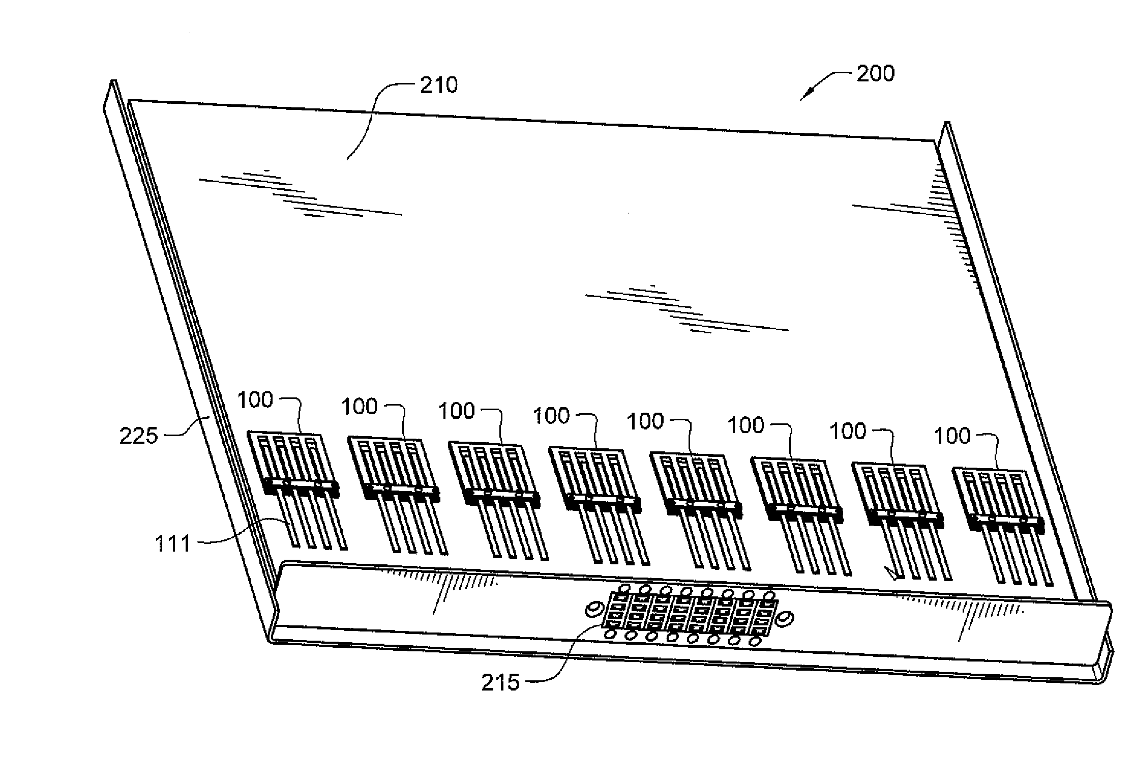
[0025]In accordance with the invention, an optical transceiver system is provided that comprises multiple parallel transceiver modules that are mounted on a card. The transceiver card is small in terms of spatial dimensions, has very good heat dissipation characteristics, and is capable of simultaneously transmitting and receiving data at a rate equal to or greater than approximately 1 Tb / s. A plurality of the transceiver systems may be interconnected to achieve a communications hub system having even higher bandwidths. In addition, the transceiver system may be configured such that each card has a routing controller mounted thereon for performing router functions. The router functions include, for example: causing signals received by one transceiver module on the card to be routed to and transmitted by another of the transceiver modules; causing signals received by one transceiver module on the card to be retransmitted by the same transceiver module over one of its optical transmit...


PUM


Abstract

An optical transceiver system is provided that comprises multiple parallel transceiver modules that are mounted on a card. The transceiver card is small in terms of spatial dimensions, has very good heat dissipation characteristics, and is capable of simultaneously transmitting and receiving data at a rate equal to or greater than approximately one Tb per second (1 Tb / s). A plurality of the transceiver systems may be interconnected to achieve a communications hub system having even higher bandwidths. In addition, the transceiver system may be configured such that each card has a routing controller mounted thereon for performing router functions. The router functions include, for example: causing signals received by one transceiver module on the card to be routed to and transmitted by another of the transceiver modules; causing signals received by one transceiver module on the card to be retransmitted by the same transceiver module over one of it's optical transmit channels; and causing signals received by one transceiver module on the card to be routed to and transmitted by a transceiver module on a different card.

Description

TECHNICAL FIELD OF THE INVENTION[0001]The invention relates to optical communications systems. More particularly, the invention relates to a transceiver system comprising a card on which multiple parallel transceiver modules are mounted for simultaneously transmitting and receiving information at a rate equal to or greater than approximately one terabit per second.BACKGROUND OF THE INVENTION[0002]FIG. 1 illustrates a block diagram of a parallel transceiver module 2 currently used in optical communications, which has multiple transmit and receive channels. The transceiver module 2 includes a transmitter portion 3 a receiver portion 4. The transmitter and receiver portions 3 and 4 are controlled by a transceiver controller 6. The transmitter portion 3 comprises components for transmitting data in the form of amplitude modulated optical signals over multiple fibers (not shown). The transmitter portion includes a laser driver 11 and a plurality of laser diodes 12. The laser driver 11 ou...

Claims


Application Information

Patent Timeline
Patent Type & Authority Applications(United States)
IPC IPC(8): H04B10/00
CPCG02B6/4201H04B10/801G02B6/4249G02B6/4246G02B6/4269G02B6/428H04B10/2589H04B10/40H04B10/43
Inventor MCCOLLOCH, LAURENCE R.
Owner AVAGO TECH INT SALES PTE LTD
Why Eureka
Try Eureka