
Prosthesis and Method for Replacing Degenerative Vertebral Portions

a technology of vertebral parts and prosthesis, which is applied in the field of prosthesis for replacing one or more portions of a vertebra, can solve the problems of degenerative spondylolisthesis, degenerative scoliosis, and spinal stenosis, and achieve the effects of reducing the risk of degeneration of the posterior spinal arch

Inactive Publication Date: 2010-10-14
WARSAW ORTHOPEDIC INC
View PDF22 Cites 38 Cited by
  • Summary
  • Abstract
  • Description
  • Claims
  • Application Information

AI Technical Summary

Benefits of technology

The prosthesis system effectively replaces degenerated spinal components, preserving motion between vertebrae and facilitating reattachment of native structures, thus addressing the limitations of existing surgical techniques.

Problems solved by technology

Such degeneration alters the mechanics of the facet joints and may cause spinal stenosis, degenerative spondylolisthesis, and degenerative scoliosis.
Moreover, the posterior spinal arch is known to degenerate due to congenital defects and / or tissue degeneration.
However, while spinal arthrodesis may alleviate the immediate symptoms, all motion between the vertebrae that are fused is lost.
Moreover, the known joint replacements tend to be overly complex and cumbersome.

Method used


Image

  • Prosthesis and Method for Replacing Degenerative Vertebral Portions
  • Prosthesis and Method for Replacing Degenerative Vertebral Portions
  • Prosthesis and Method for Replacing Degenerative Vertebral Portions

Examples


Embodiment Construction

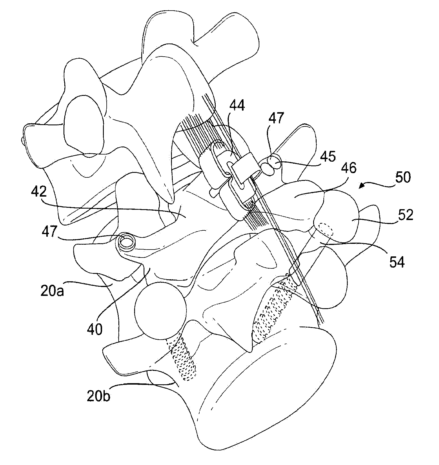
[0024]The drawings illustrate embodiments of a prosthesis for replacing one or both of a posterior arch and an intervertebral facet joint. Various embodiments of the prosthesis according to the principles of the disclosure may be used for treating any problems that lend themselves to joint and / or degenerative bone and tissue replacement.

[0025]Throughout the application, terms such as posterior, anterior, superior, inferior, rostral, and caudal are used in some embodiments to describe positions of components of the embodiments. While the meanings of such terms are generally used in the art to describe certain positions, such are used herein merely as relative positions and / or modifiers to describe relative positions. Components labeled using such terms in an illustrated embodiment are not intended to limit the scope of claims to any device or method.

[0026]A preferred embodiment of the present invention will be described with reference to FIGS. 3A, 3B, and 4-6.

[0027]FIGS. 3A and 3B de...


PUM


Abstract

A posterior arch prosthesis according to the present invention includes a main body, two transverse protuberances extending transversely from either side of the main body, articulating surfaces formed on each of the transverse protuberances, and a posterior protuberance extending posteriorly from the main body. The posterior protuberance is attached to a first vertebra from which the natural posterior arch has been removed such that the articulating surfaces are arranged in articulating contact with surfaces on an adjacent, second vertebra. The posterior protuberance includes an attachment to which native structure may be reattached upon attachment of the prosthesis to the first vertebra.

Description

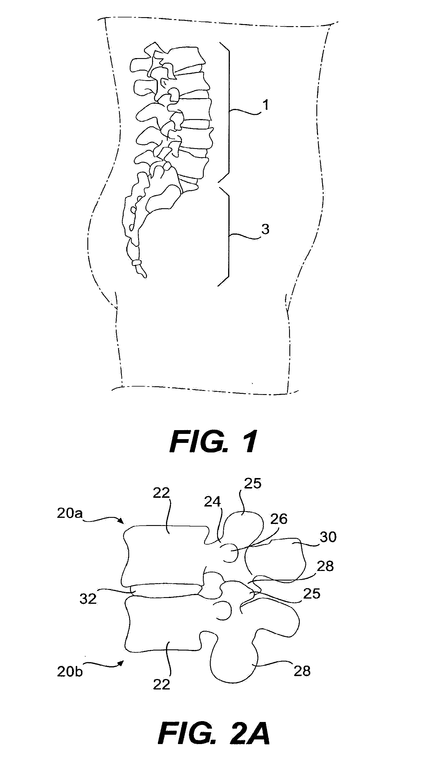
BACKGROUND OF THE INVENTION[0001]1. Field of the Invention[0002]This invention relates generally to a prosthesis for replacing one or more portions of a vertebra. More specifically, this invention relates to a device for replacement of a posterior spinal arch and one or more vertebral posterior facets.[0003]2. Description of the Related Art[0004]As is known in the art, in the human anatomy, the spine is a generally flexible column that supports compressive and tensile loads, allows for bending, and provides a place of attachment for bones (i.e., ribs), muscles, and ligaments. In general, the spine is divided into the cervical, thoracic, and lumbar spinal sections. FIG. 1 illustrates the lumbar spinal section 1 and a sacrum region 3 in a healthy human.[0005]Each section of the spine consists of individual bones, called vertebrae. FIGS. 2A and 2B depict, respectively, a side view and a posterior view of two adjacent, healthy vertebrae 20a, 20b, and FIG. 2C depicts a top view of a vert...

Claims


Application Information

Patent Timeline
Patent Type & Authority Applications(United States)
IPC IPC(8): A61F2/44
CPCA61B17/7067A61B17/842A61B17/8605A61F2/4405A61F2002/3092A61F2002/30784A61F2002/3085A61F2002/30909A61F2002/30578
Inventor EISERMANN, LUKAS G.PETERMAN, MARCALLARD, RANDALL N.
Owner WARSAW ORTHOPEDIC INC
Learn More