
Stand column, in particular music stand column or microphone stand column

a technology for standing columns and microphones, which is applied in the direction of reading desks, pulpits, rod connections, etc., can solve the problems of reducing the risk reducing the chance of rolling elements deforming the other tubes, and not being suitable for tubes with a round cross section

Inactive Publication Date: 2010-09-30
KONIG & MEYER
View PDF5 Cites 13 Cited by
  • Summary
  • Abstract
  • Description
  • Claims
  • Application Information

AI Technical Summary

Benefits of technology

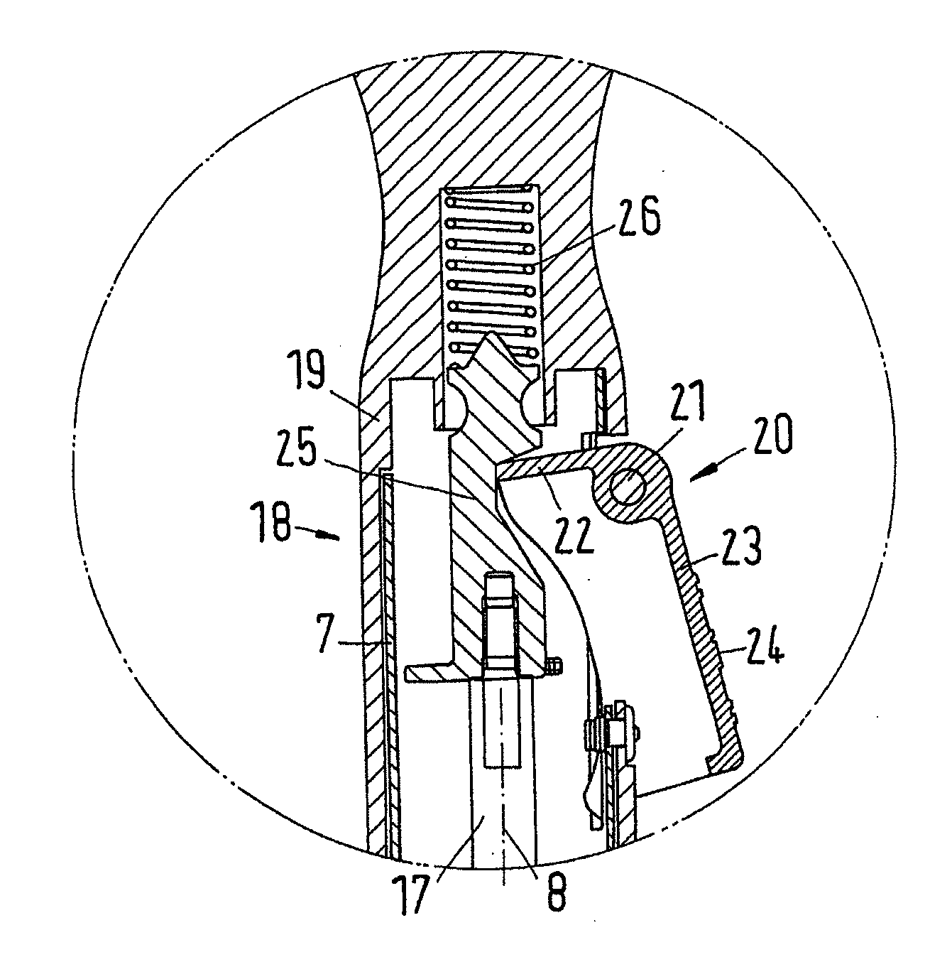
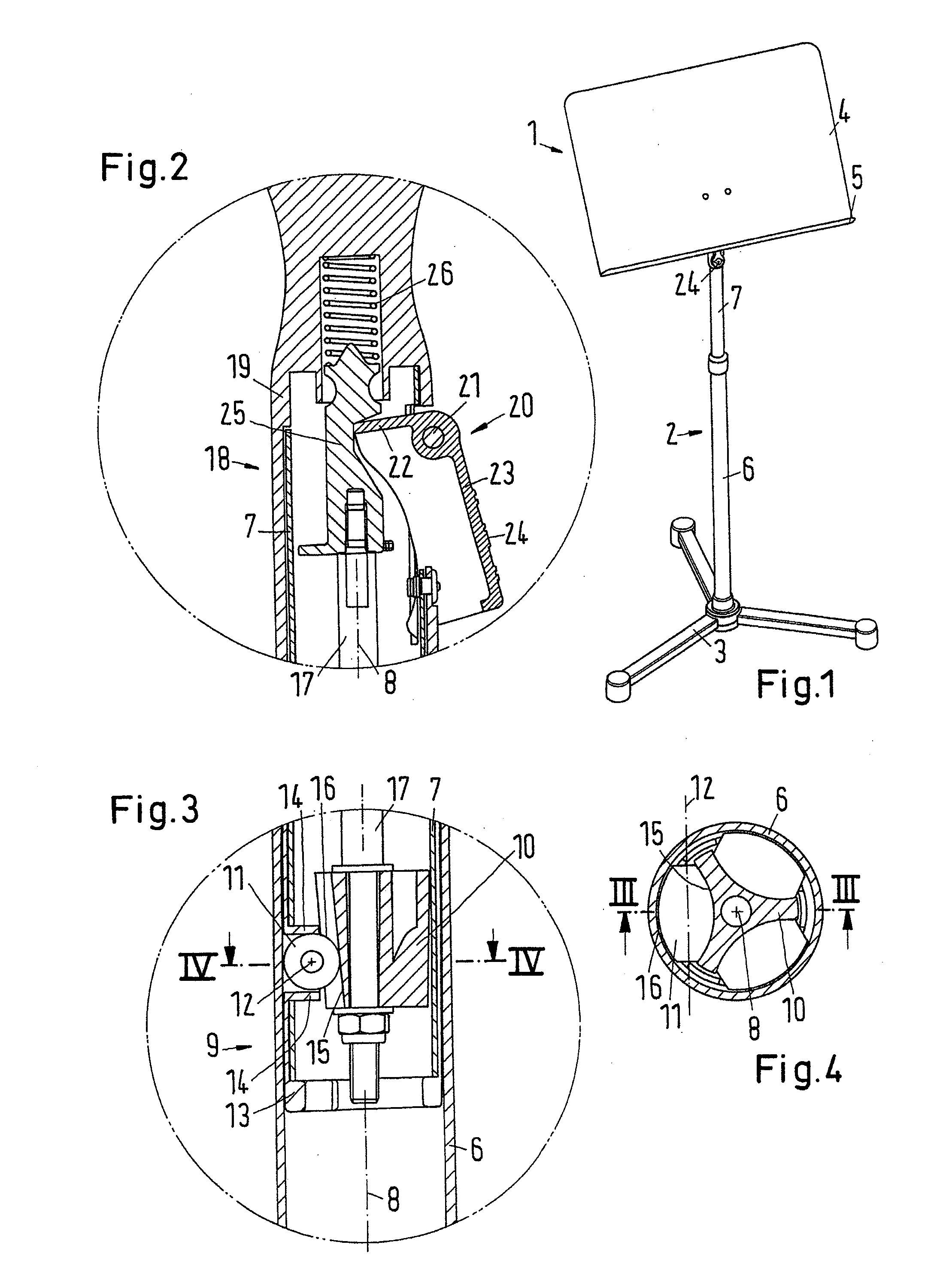
[0010]With an embodiment of this type, the length of the stand column can be easily changed by loosening the clamping device. This can be carried out with the same hand that also holds the one tube. The clamping device operates with friction force. The clamping body presses on the rolling element. In turn, the rolling element bears against the other tube. The friction between the rolling element and the other tube on the one hand and the rolling element and the clamping body on the other hand prevents a reciprocal alignment of the two tubes from being changed when the clamping device has become active. In order to loosen the clamping device, the clamping body needs only to be displaced a small distance so that the friction is reduced. Due to the curved circumferential wall of the rolling element, a relatively large contact zone results between the rolling element and the other tube. This contact zone extends over virtually the entire axial length of the rolling element. This results in a relatively large area over which the friction force can act. Thus, relatively large forces can be applied without making the local compressive stresses excessively large. This keeps the risk low that the rolling element will deform the other tube. This risk exists, for example, with the use of spherical rolling elements, which bear against the other tube as it were only with a punctiform contact surface and therefore are not very suitable for tubes with a round cross section.
[0012]In a preferred embodiment, the other tube has a circular cross section and the curvature of the circumferential wall of the rolling element follows a circular line. This embodiment has the advantage that the inner tube and the outer tube can be fixed in any desired rotational angle position to one another, so that a music stand or also a microphone can be turned in a desired direction.
[0015]Preferably, the rolling element is made of a plastic. A plastic is generally somewhat softer than a metal. When the clamping body is then displaced such that it clamps the rolling element between itself and the other tube, the rolling element can be somewhat deformed so that the originally approximately linear mounting region widens to form a surface. This further improves the clamping.
[0016]It is preferable that the rolling element is made of polyurethane or a plastic with the same recovery behavior as polyurethane. The rolling element can then easily be deformed when the clamping body acts thereon, i.e., it is somewhat flattened in order to form a larger contact zone between the other tube on the one hand and the mounting surface of the clamping body on the other hand. When the clamping force is reduced, the rolling element returns to its rotationally symmetrical form again, i.e., it forms a roller again that bears against the other tube and can unroll there.
[0019]Preferably, the release device has an actuating lever. The actuating lever can be pivoted in order to displace the clamping body. The actuation of an actuating lever is easily possible in single-handed operation.
[0021]Preferably, a return spring acts on the actuating lever. This return spring ensures that the clamping device becomes active when the user releases the actuating lever. It is thus ensured in a simple manner that the inner tube and the outer tube are fixed in their position relative to one another as soon as the user releases the actuating lever.

Problems solved by technology

This results in a relatively large area over which the friction force can act.
This keeps the risk low that the rolling element will deform the other tube.
This risk exists, for example, with the use of spherical rolling elements, which bear against the other tube as it were only with a punctiform contact surface and therefore are not very suitable for tubes with a round cross section.

Method used


Image

  • Stand column, in particular music stand column or microphone stand column
  • Stand column, in particular music stand column or microphone stand column

Examples


Embodiment Construction

[0041]The particulars shown herein are by way of example and for purposes of illustrative discussion of the embodiments of the present invention only and are presented in the cause of providing what is believed to be the most useful and readily understood description of the principles and conceptual aspects of the present invention. In this regard, no attempt is made to show structural details of the present invention in more detail than is necessary for the fundamental understanding of the present invention, the description taken with the drawings making apparent to those skilled in the art how the several forms of the present invention may be embodied in practice.

[0042]FIG. 1 shows a music stand 1 with a stand column 2. A foot 3, which is provided at the lower end of stand column 2, can include a number of supporting legs, e.g., three supporting legs as in the illustrated embodiment. A rest 4 for music is provided at an upper end of stand column 2, and includes a support ledge 5 a...


PUM


Abstract

A stand column includes two tubes having longitudinal axes and curved tube walls surrounding the longitudinal axes. The two tubes include an inner tube guidable in a telescoping manner in an outer tube. A clamping device is structured and arranged to fix the inner tube in various positions with respect to the outer tube, and includes at least one rolling element with a rotational axis oriented parallel to a normal to the longitudinal axes. The at least one rolling element is positioned between at least one clamping body arranged on one of the two tubes and the other of the two tubes, and has a circumferential wall with a curvature parallel to the rotation axis that is adapted to a curvature of the other tube.

Description

CROSS-REFERENCE TO RELATED APPLICATIONS[0001]The present application claims priority under 35 U.S.C. §119 of European Patent Application No. EP 09 004 447.0, filed on Mar. 27, 2009, the disclosure of which is expressly incorporated by reference herein in its entirety.BACKGROUND OF THE INVENTION[0002]1. Field of the Invention[0003]The invention relates to a stand column, in particular, a music stand column or microphone stand column, with two tubes, i.e., an inner tube guided in an outer tube in a telescoping manner, and a clamping device, with which the inner tube can be fixed in various positions with respect to the outer tube. The two tubes respectively have a longitudinal axis and curved tube walls surrounding the longitudinal axis.[0004]2. Discussion of Background Information[0005]During musical performances it is often necessary to place the music (sheet music) needed by a musician on a music stand. This music stand should be adjustable in height so the music can be seen well b...

Claims


Application Information

Patent Timeline
Patent Type & Authority Applications(United States)
IPC IPC(8): F16M11/26
CPCA47B19/002F16B7/1409F16M2200/028F16M11/2014F16M11/28
Inventor LIPPERT, HELMUTREICHERT, PETER
Owner KONIG & MEYER
Learn More