
Wireless FM repeater system

a repeater system and wireless technology, applied in the field of low-power transmitters and receivers, can solve the problems of product end, marginal audio input from these audio sources to most conventional vehicle fm stereo equipment, and most vehicle audio equipment do not even have provisioning

Inactive Publication Date: 2010-09-23
L S RES
View PDF4 Cites 57 Cited by
  • Summary
  • Abstract
  • Description
  • Claims
  • Application Information

AI Technical Summary

Problems solved by technology

In particular, attempting to couple audio inputs from these audio sources to most conventional vehicle FM stereo equipment is marginal at best.
Most vehicle audio equipment do not even have a provision for supporting the direct coupling with such auxiliary audio devices.
Although very successful, this product is now reaching its end of life due to the fact that cassette players have now been replaced by CD players in most vehicles built after 2000.
However, there are limitations to such devices.
A transmitter that is operating at the FCC power limit cannot provide a strong enough signal to the car radio to provide high quality reception.
This will always be the primary limitation of all FM transmitters currently on the market.
Consequently, it is necessary to locate the FM transmitter very close to the vehicle antenna which is impractical.
Since the majority of cars have their radio antenna located on an outside fender, rooftop or rear window it is not possible to satisfy both requirements and, as a result, the performance will be degraded.
Moreover, even with the elevated power levels, the general response from consumers in that the overall performance is still very poor.
Reviews (e.g., by Amazon and various FM transmitter web / blog sites) of these types of devices are filled with complaints about their performance.

Method used


Image

  • Wireless FM repeater system
  • Wireless FM repeater system
  • Wireless FM repeater system

Examples


Embodiment Construction

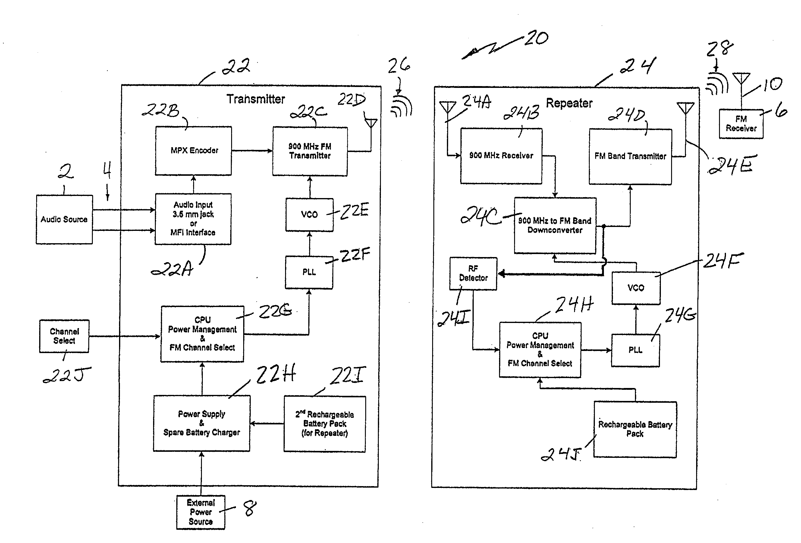
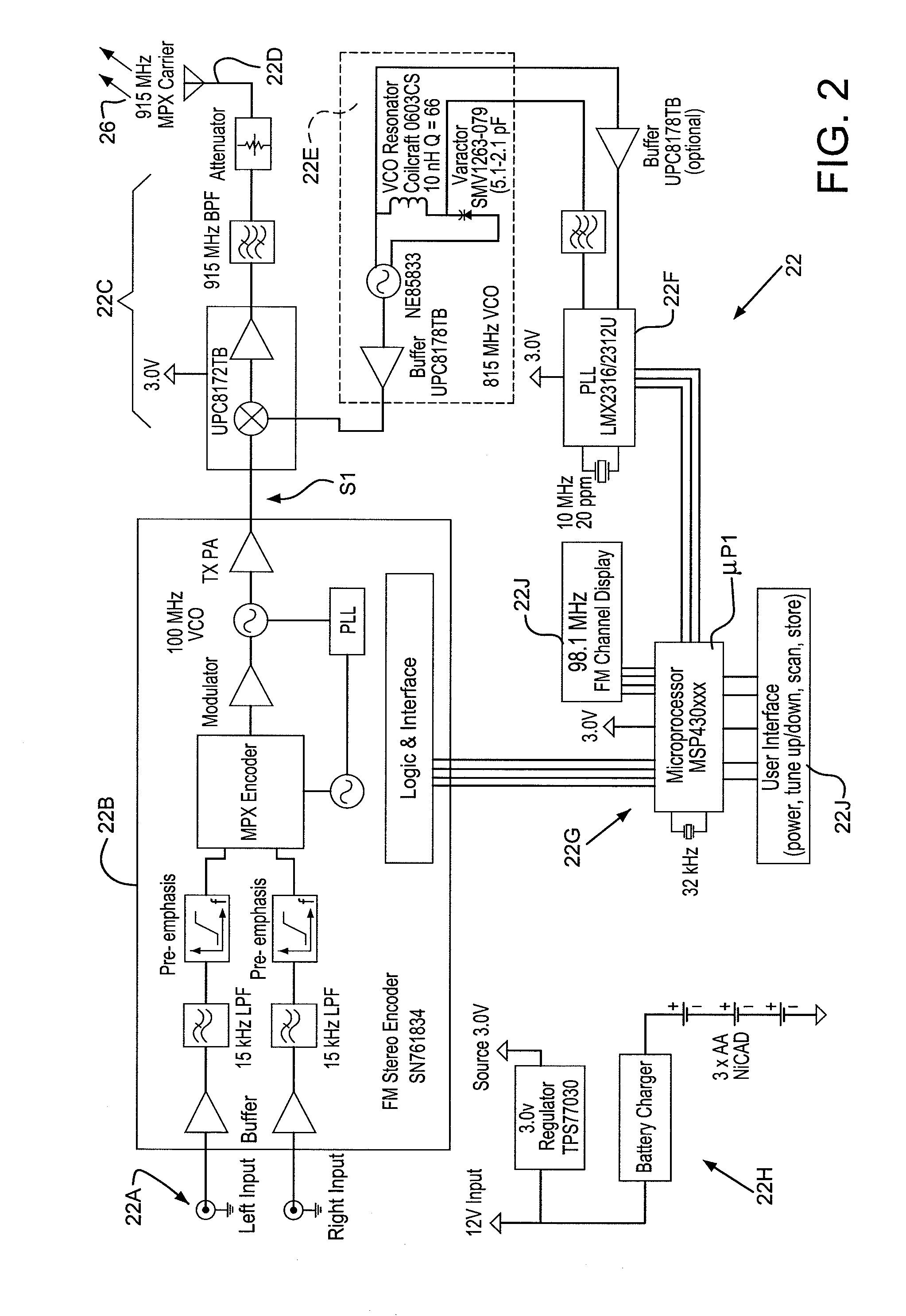
[0033]As will be discussed in detail later, the invention of the present application involves the use of a transmitter, coupled to the audio source, that wirelessly transmits the audio source signals at a high frequency (e.g., 902-928 MHz, 2.4-2.483 GHz, 434 / 868 MHz, etc.) to a repeater located adjacent the vehicle's audio system antenna and wherein the repeater downconverts the high frequency carrier and includes an FM transmitter that wirelessly transmits the audio source signal, in compliance with government regulations, to the vehicle's audio system antenna without signal degradation. The invention accomplishes this without the need to demodulate any signals, without the use of wires (other than to couple the audio source to the invention or enhance repeater-vehicle antenna coupling), while minimizing current consumption (e.g., ≦10 mA of current draw on the external power source) and while complying with government regulations. In particular, where the 902-928 MHz carrier signal...


PUM


Abstract

A wireless FM repeater system for converting the audio signal from a portable audio source (e.g., iPod, MP3 player, a cell phone or satellite radio, etc.) and transmitting it to the FM tuner of a vehicle stereo system where access to a hard-wired input jack does not exist. The system includes a transmitter, coupled to the audio source, that transmits the audio source signals at a high frequency (e.g., 902-928 MHz, 2.4-2.483 GHz, 434 / 868 MHz) to a repeater located adjacent the vehicle's audio system antenna and wherein the repeater downconverts, without demodulation, the high frequency carrier and includes an FM transmitter that transmits the audio source signal, in compliance with government regulations, to the vehicle's audio FM system, via the vehicle's FM antenna, without signal degradation.

Description

BACKGROUND OF THE INVENTION[0001]1. Field of Invention[0002]The current invention relates to low power transmitters and receivers and more particularly, to a low power transmitter / repeater system for use in a vehicle for transmitting portable audio source outputs to the vehicle's radio system that lacks auxiliary input jacks.[0003]2. Description of Related Art[0004]With the rapid growth in hand-held multi-media devices, especially MP3 players, the desire to integrate these devices with existing vehicle systems has also greatly increased. In particular, attempting to couple audio inputs from these audio sources to most conventional vehicle FM stereo equipment is marginal at best. Most vehicle audio equipment do not even have a provision for supporting the direct coupling with such auxiliary audio devices.[0005]One available solution is the cassette adapter (U.S. Pat. No. 4,734,897 (Schotz)) developed by L.S. Research, Inc. (now L.S. Research, LLC, the assignee of the present applicat...

Claims


Application Information

Patent Timeline
Patent Type & Authority Applications(United States)
IPC IPC(8): H04B7/15
CPCH04B1/034
Inventor BUCZKIEWICZ, ROBERT T.STEINIKE, WILLIAM R.
Owner L S RES
Learn More