Railway brake shoe
a brake shoe and rail technology, applied in the direction of brake elements, brake members, friction linings, etc., can solve the problems of difficult or inability to obtain the benefits of metal inserts
- Summary
- Abstract
- Description
- Claims
- Application Information
AI Technical Summary
Benefits of technology
Problems solved by technology
Method used
Image
Examples
Embodiment Construction
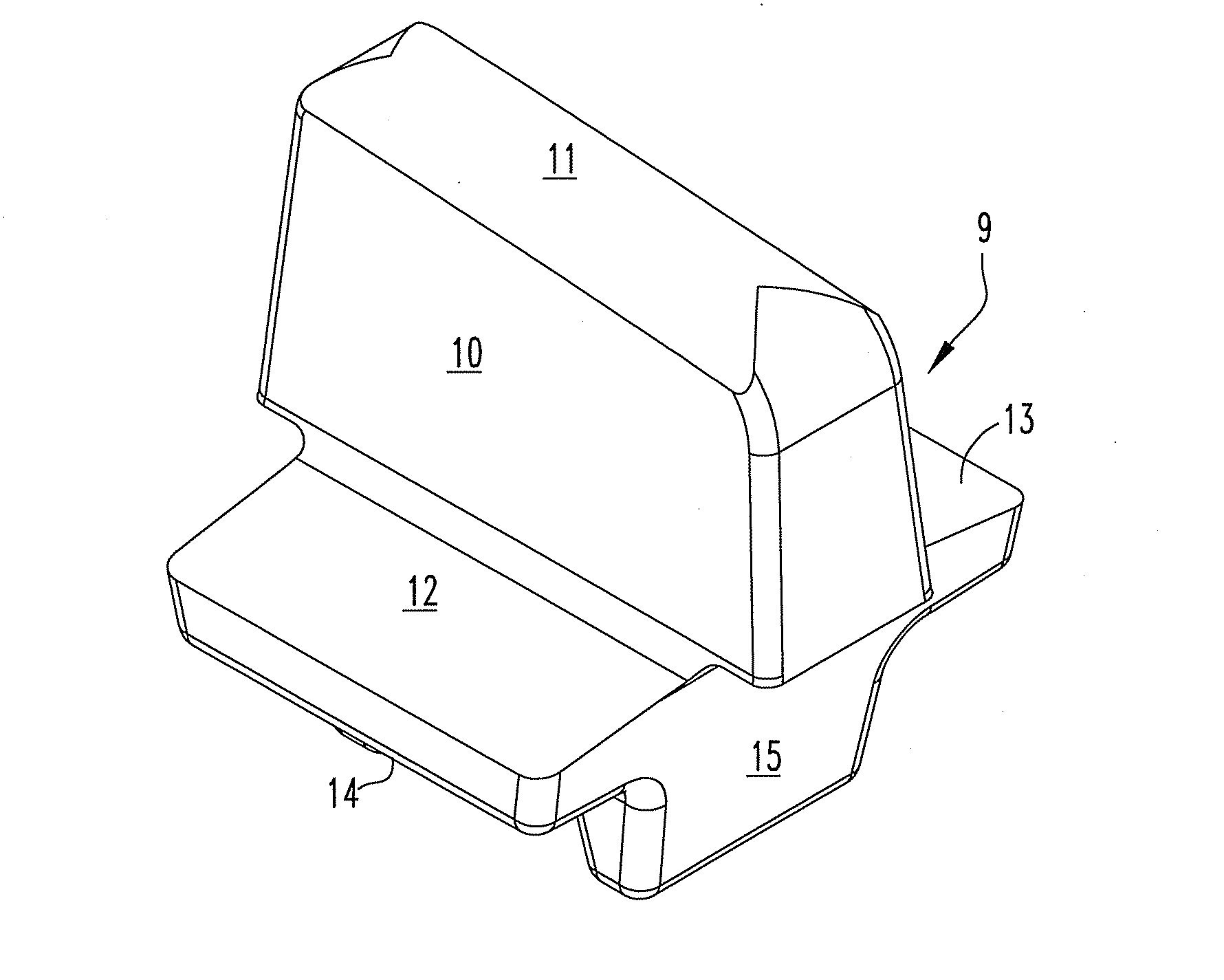
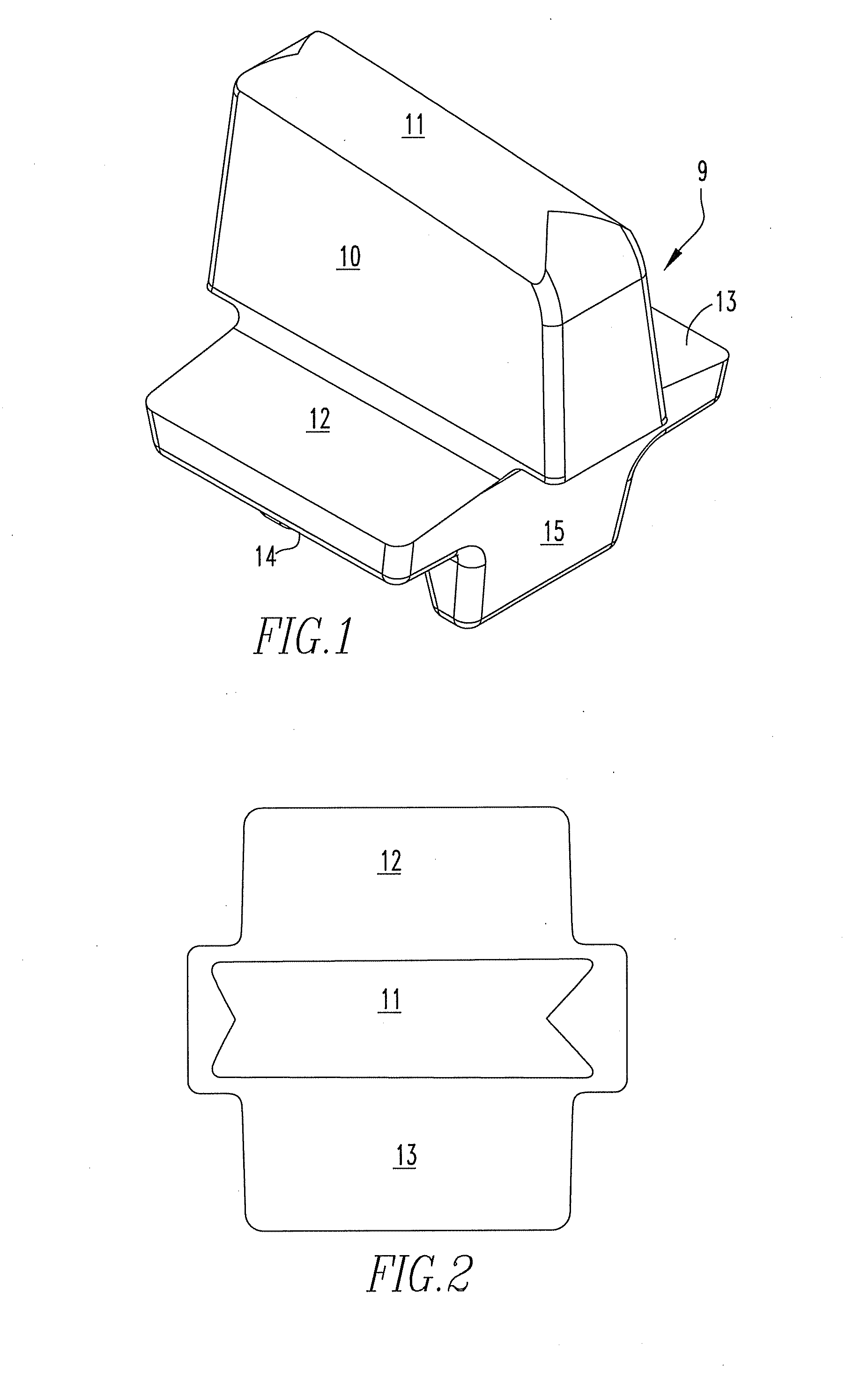
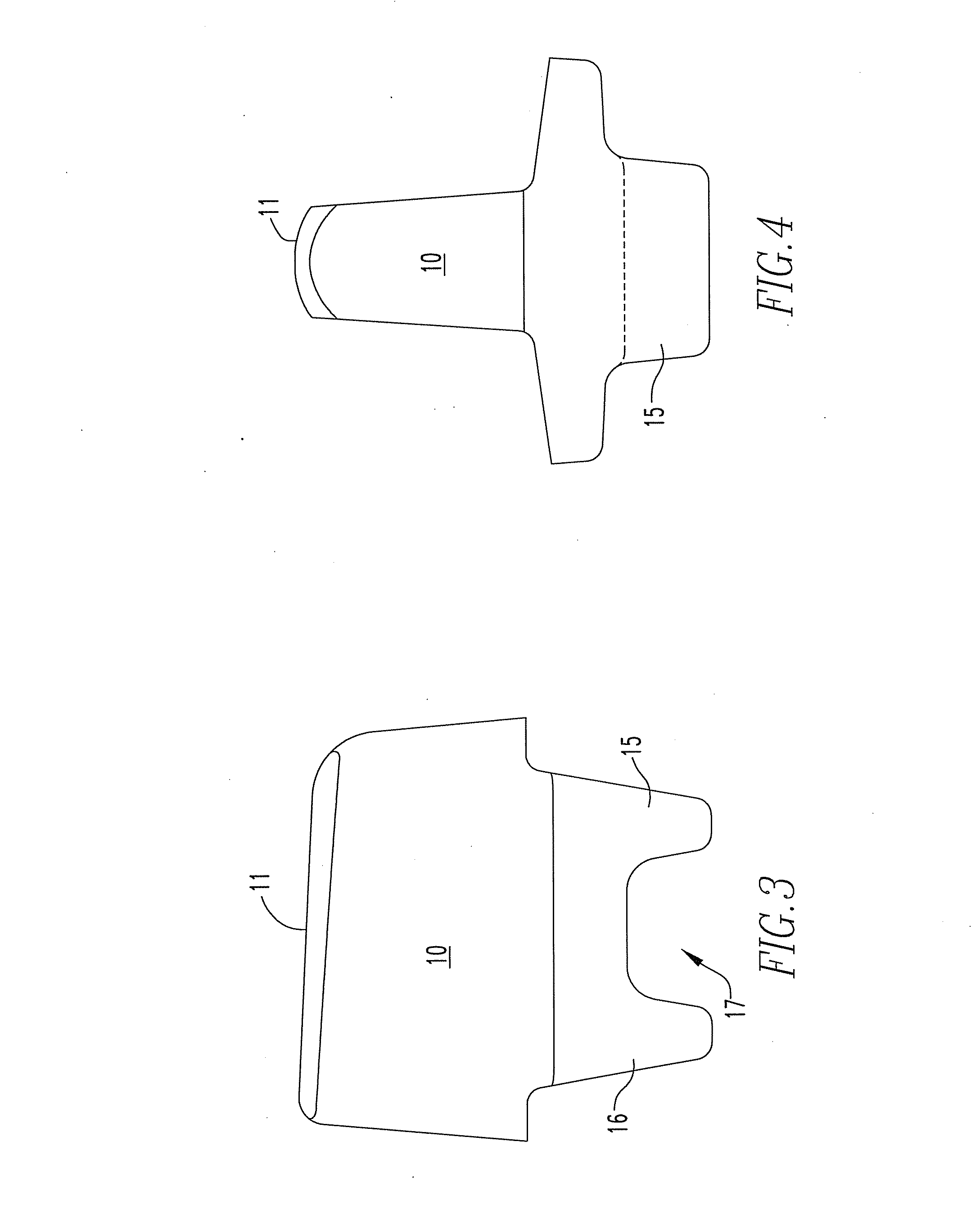
[0025]Referring now to FIGS. 1 to 4, there is shown an insert for a brake shoe without a metal backing. A brake shoe is defined by a friction surface for bearing upon a wheel tread and an opposed back surface for being placed in contact with and secured to a brake head. A metal insert 9 comprises a main body 10 having a friction face 11 for lying in the friction surface of a brake shoe. The main body 10 extends away from the friction face. Two wing-like extensions 12, 13 are integral with the main body and on opposite sides of the main body and extending away therefrom. The wing-like extensions have back faces 14 for being positioned adjacent to the back surface of the brake shoe and providing brake head support. Two generally parallel radially extending flanges 15, 16 are integral with the main body 10 and / or the wing-like extensions 12, 13. The parallel flanges 15, 16 are sized for extending beyond the back surface of a brake shoe thus defining a keyway 17.
[0026]Referring to FIGS....
PUM
 Abstract
Description
Claims
Application Information
 - Generate Ideas
- Intellectual Property
- Life Sciences
- Materials
- Tech Scout
- Unparalleled Data Quality
- Higher Quality Content
- 60% Fewer Hallucinations
Browse by: Latest US Patents, China's latest patents, Technical Efficacy Thesaurus, Application Domain, Technology Topic, Popular Technical Reports.
© 2025 PatSnap. All rights reserved.Legal|Privacy policy|Modern Slavery Act Transparency Statement|Sitemap|About US| Contact US: help@patsnap.com


