
Fastening device for system irons

a technology of fastening device and system iron, which is applied in the direction of stand/trestle, kitchen equipment, and paper towels, etc., can solve the problem of small risk of hand contact with the soleplate of the user's hand, and achieve the effect of improving the safety of the fastening device, stable engagement, and precise positioning of the iron on the bas

Inactive Publication Date: 2010-08-12
KONINKLIJKE PHILIPS ELECTRONICS NV
View PDF13 Cites 9 Cited by
  • Summary
  • Abstract
  • Description
  • Claims
  • Application Information

AI Technical Summary

Benefits of technology

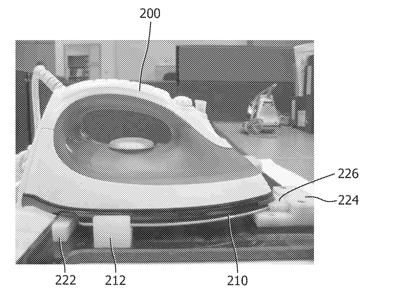
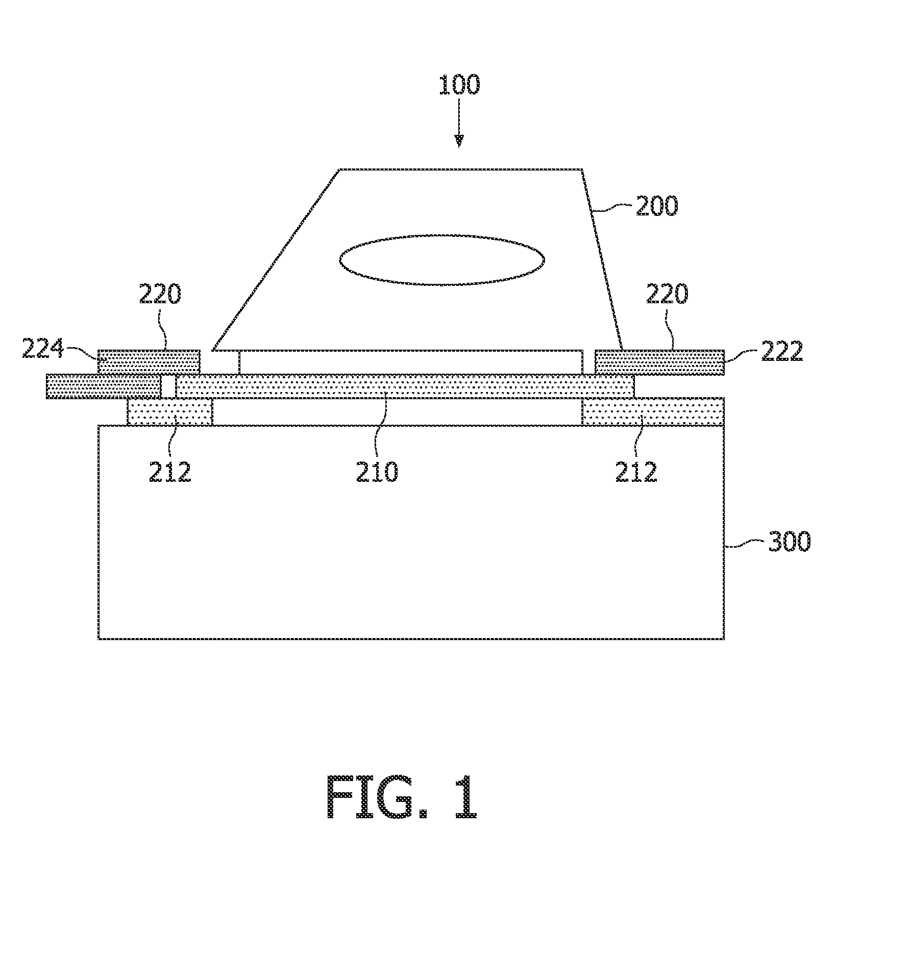
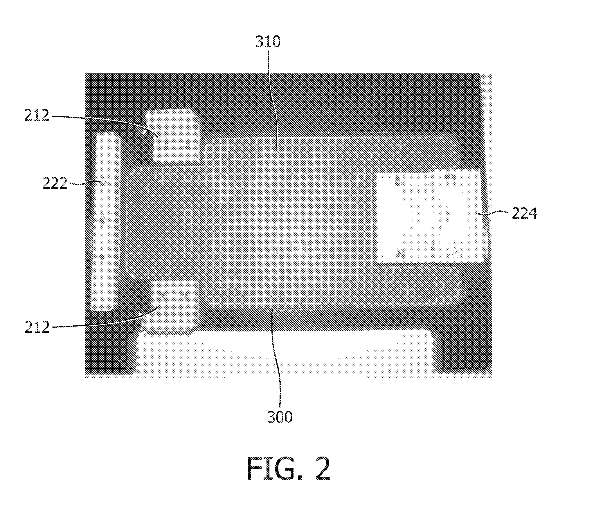
The invention is a system iron with a fastening device for securely locking the iron to a base. The fastening device includes two engagement members that are biased towards each other, allowing the user to easily lock the iron with just one hand. The engagement members can engage the front and rear parts of the iron, ensuring stability during transportation. The displaceable engagement member can be locked in place to improve safety. The base can also have a steam generator for ironing and the system iron can be transported and stored safely after use.

Problems solved by technology

When doing so, the user's hands do not come close to the hot soleplate, so that the risk of contact of the user's hand with the soleplate is very small.

Method used


Image

  • Fastening device for system irons
  • Fastening device for system irons
  • Fastening device for system irons

Examples


Embodiment Construction

[0017]The present invention will be described with respect to particular embodiments and with reference to certain drawings, but the invention is not limited thereto. Any reference signs in the claims shall not be construed as limiting the scope. The drawings described are only schematic and are non-limiting. In the drawings, the size of some of the elements may be exaggerated and not drawn to scale for illustrative purposes. Where the term “comprising” is used in the present description and claims, it does not exclude other elements or steps. Where an indefinite or definite article is used when referring to a singular noun e.g. “a” or “an”, “the”, this includes a plural of that noun unless something else is specifically stated.

[0018]Furthermore, the terms first, second, third and the like in the description and in the claims, are used for distinguishing between similar elements and not necessarily for describing a sequential or chronological order. It is to be understood that the t...


PUM


Abstract

A system iron comprises an iron and a base that has a receiving area for receiving the iron. The base comprises a fastening device for fastening the iron to the base. The fastening device includes a first engagement member and a second engagement member arranged at mutually opposite sides of the receiving area. At least one of the engagement members is displaceable in a direction away from the other engagement member and is biased towards the other engagement member. With such a fastening device, a user can safely and conveniently lock the iron to the base using just one of his hands for gripping the main grip portion of the iron.

Description

FIELD OF THE INVENTION[0001]This invention relates to system irons, more in particular to a fastening device for the system irons.BACKGROUND OF THE INVENTION[0002]After an ironing operation, a system iron including an iron and a base is carried to be kept in a cabinet or the like until next use. At the time of transport, if the iron is not fastened to the base properly, there is a possibility of the iron and the base getting apart and falling down. In order to prevent this, it is necessary to make sure of sufficient coupling before transporting the system iron. In conventional system irons care must be taken when placing the iron on the base and fastening the iron to the base as there may be a chance of a user touching the hot iron.[0003]WO2006027464 describes an ironing appliance comprising an iron and a portable base provided with a surface for setting down the iron. The iron comprises a soleplate on which a body with an integrated handle is mounted. The base comprises means for i...

Claims


Application Information

Patent Timeline
Patent Type & Authority Applications(United States)
IPC IPC(8): D06F75/00D06F75/40
CPCD06F75/40
Inventor MA, MUN THOHJANAKIRAMAN, CHANDRA MOHANPLANTINGA, RONALD ALBERTBOUHUYS, L.CHU, WA
Owner KONINKLIJKE PHILIPS ELECTRONICS NV
Learn More