Band clamp for elongated member
- Summary
- Abstract
- Description
- Claims
- Application Information
AI Technical Summary
Benefits of technology
Problems solved by technology
Method used
Image

Examples
Embodiment Construction
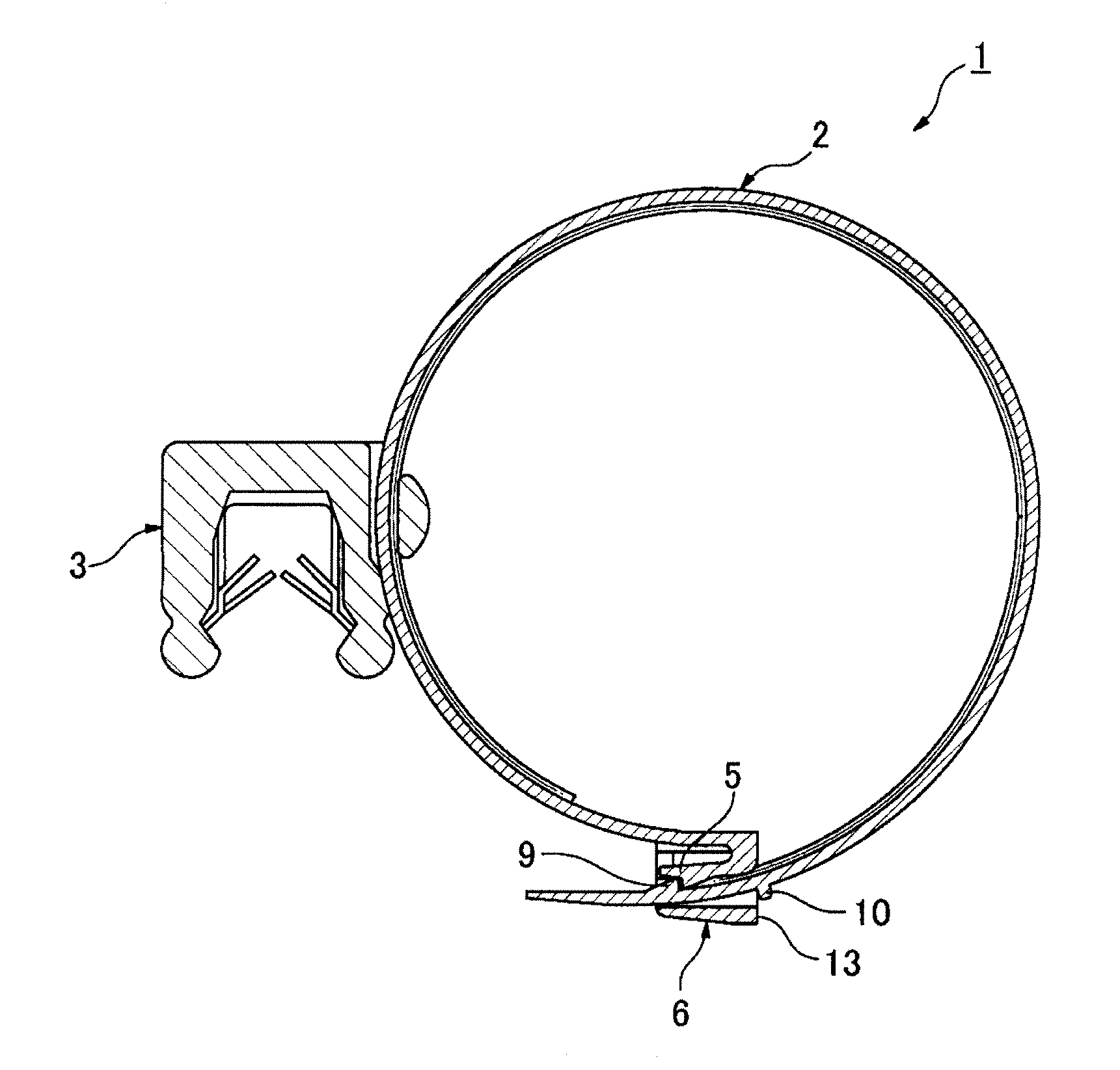
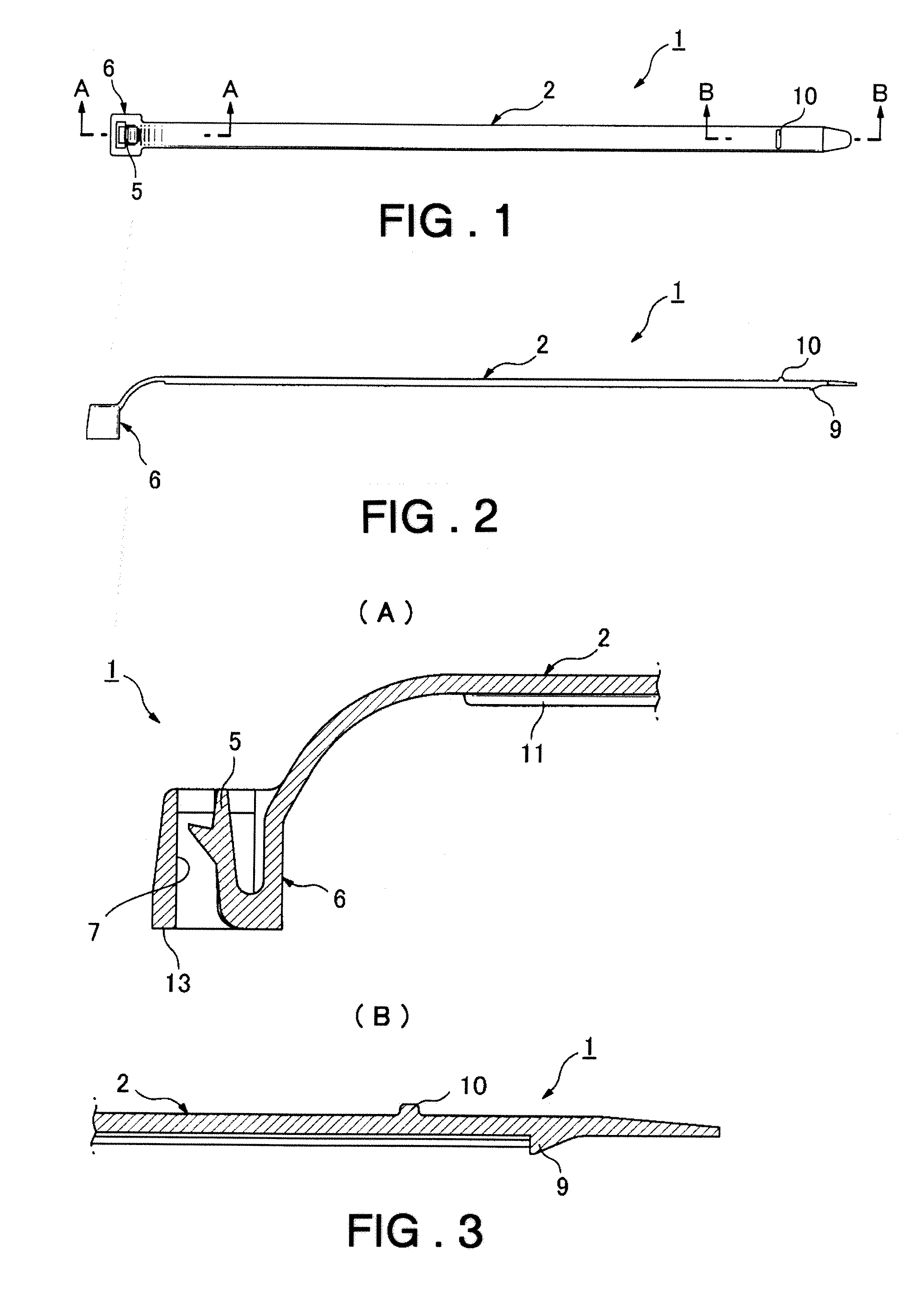
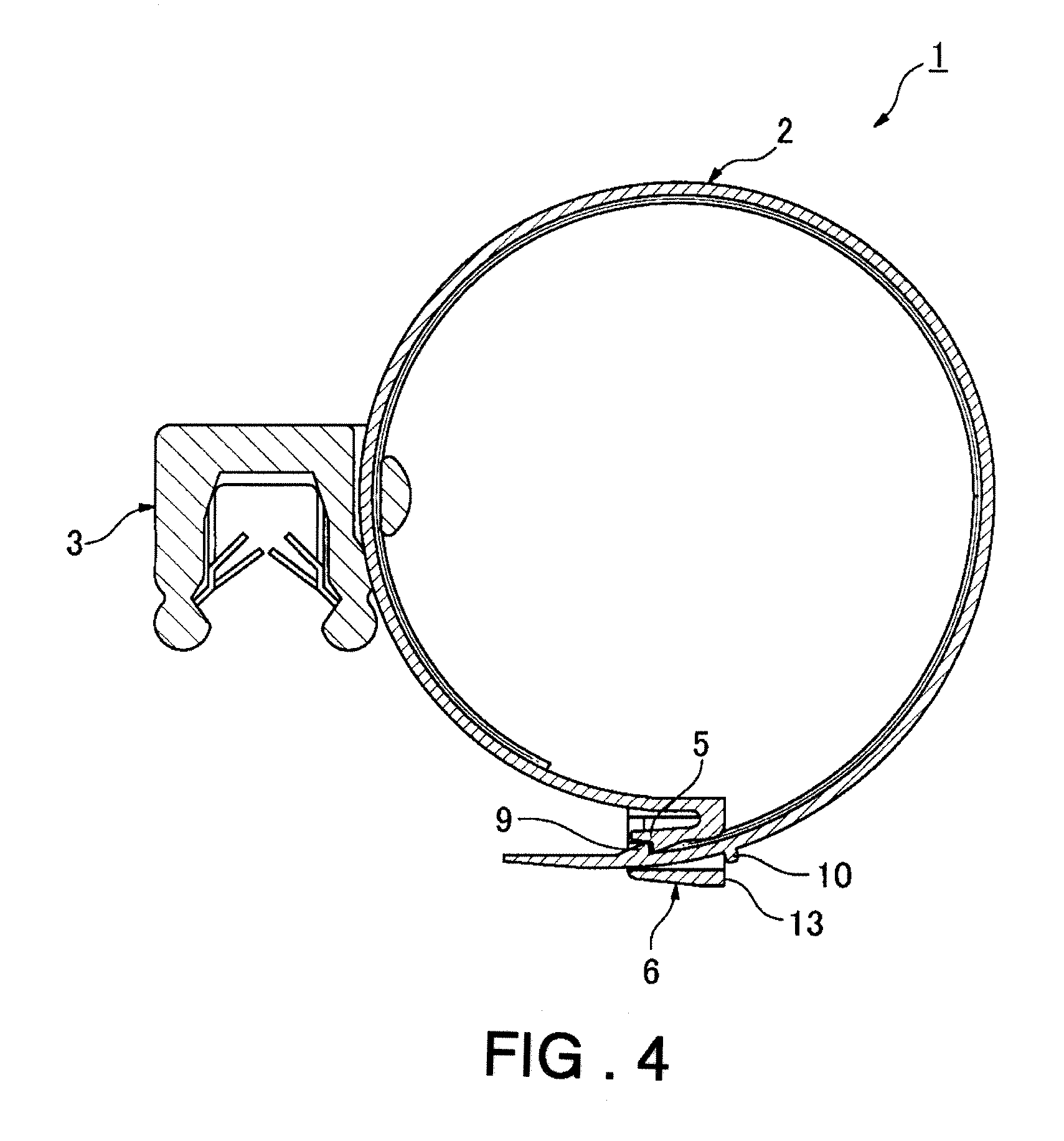
[0018]A band clamp 1 relating to one embodiment of the present invention is now described with reference to the drawings. In FIGS. 1 to 3, the band clamp 1 is diagrammed in its prior-to-use condition. In FIG. 4, how the band clamp 1 is wound about a long member such as a wire harness (not shown) to effect holding is diagrammed, with a clip 3 connected to a band 2 for connecting the long member to the member being attached to such as an automobile body panel.
[0019]In FIGS. 1 to 3, the band clamp 1 is a product that is integrally molded of a hard plastic. The band clamp 1 has a band 2 formed as a narrow, flat, belt-shaped member, and a lock 6, formed at one end of the band 2, having a latching pawl 5, for locking the condition wherein the band 2 is wound about the outer circumference of the long member such as a wire harness.
[0020]The lock 6 has a tubular band receptacle 7 through which the band 2 is passed, and a latching pawl 5 for latching the band 2, that has been accepted by the ...
PUM
 Abstract
Description
Claims
Application Information
 - R&D
- Intellectual Property
- Life Sciences
- Materials
- Tech Scout
- Unparalleled Data Quality
- Higher Quality Content
- 60% Fewer Hallucinations
Browse by: Latest US Patents, China's latest patents, Technical Efficacy Thesaurus, Application Domain, Technology Topic, Popular Technical Reports.
© 2025 PatSnap. All rights reserved.Legal|Privacy policy|Modern Slavery Act Transparency Statement|Sitemap|About US| Contact US: help@patsnap.com