
Cartridge and analyzing system

a technology of analyzing system and cartridge, which is applied in the direction of container/bottle construction, rigid containers, packaging goods, etc., can solve the problems of deteriorating operability, complicated configuration of the cartridge, and desirably small tools, so as to reduce the complexity of the configuration of the cartridge and the analyzer, reduce the cost of the analysis tool, and enhance the operability of the user

Active Publication Date: 2010-08-05
ARKRAY INC
View PDF4 Cites 2 Cited by
  • Summary
  • Abstract
  • Description
  • Claims
  • Application Information

AI Technical Summary

Benefits of technology

[0009]The present invention aims to cost effectively miniaturize the analyzing tool while enhancing the operability of the user, and suppressing complication of the configuration of the cartridge and the analyzer, enlargement, and increase in number of parts.Means for Solving the Problems

Problems solved by technology

Such an analyzing tool is desirably small in view of material cost, production equipment expense, production equipment installation area, transportation cost, convenience of the user in carrying around, and the like.
However, if the analyzing tool is small, operability deteriorates when the user attaches the analyzing tool to the analyzer or detaches the used analyzing tool from the analyzer.
However, in the configuration of taking out the analyzing tool by operating the operation unit as in the cartridge described in Patent Document 1, the number of parts increases as the operation unit and the parts coupled thereto are necessary, and furthermore, the configuration of the cartridge becomes complicating.
Thus, the manufacturing cost of the portion other than the analyzing tool in the cartridge becomes high even if the analyzing tool is miniaturized and the manufacturing cost is reduced.
In the configuration of accommodating a plurality of analyzing tools and projecting out the sample spotting portion of the desired analyzing tool to the outside of the analyzer as in the analyzer described in Patent Document 2, the device configuration becomes complicating and the manufacturing cost becomes high.

Method used


Image

  • Cartridge and analyzing system
  • Cartridge and analyzing system
  • Cartridge and analyzing system

Examples


Embodiment Construction

[0054]The present invention will be specifically described below with reference to the drawings.

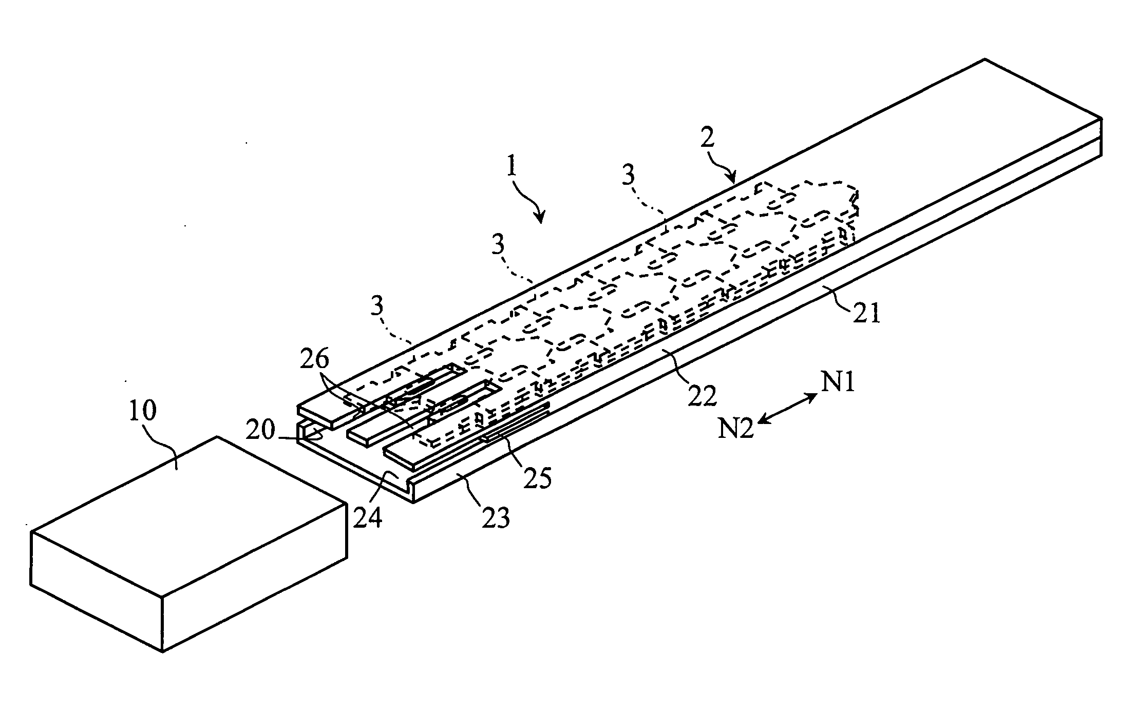
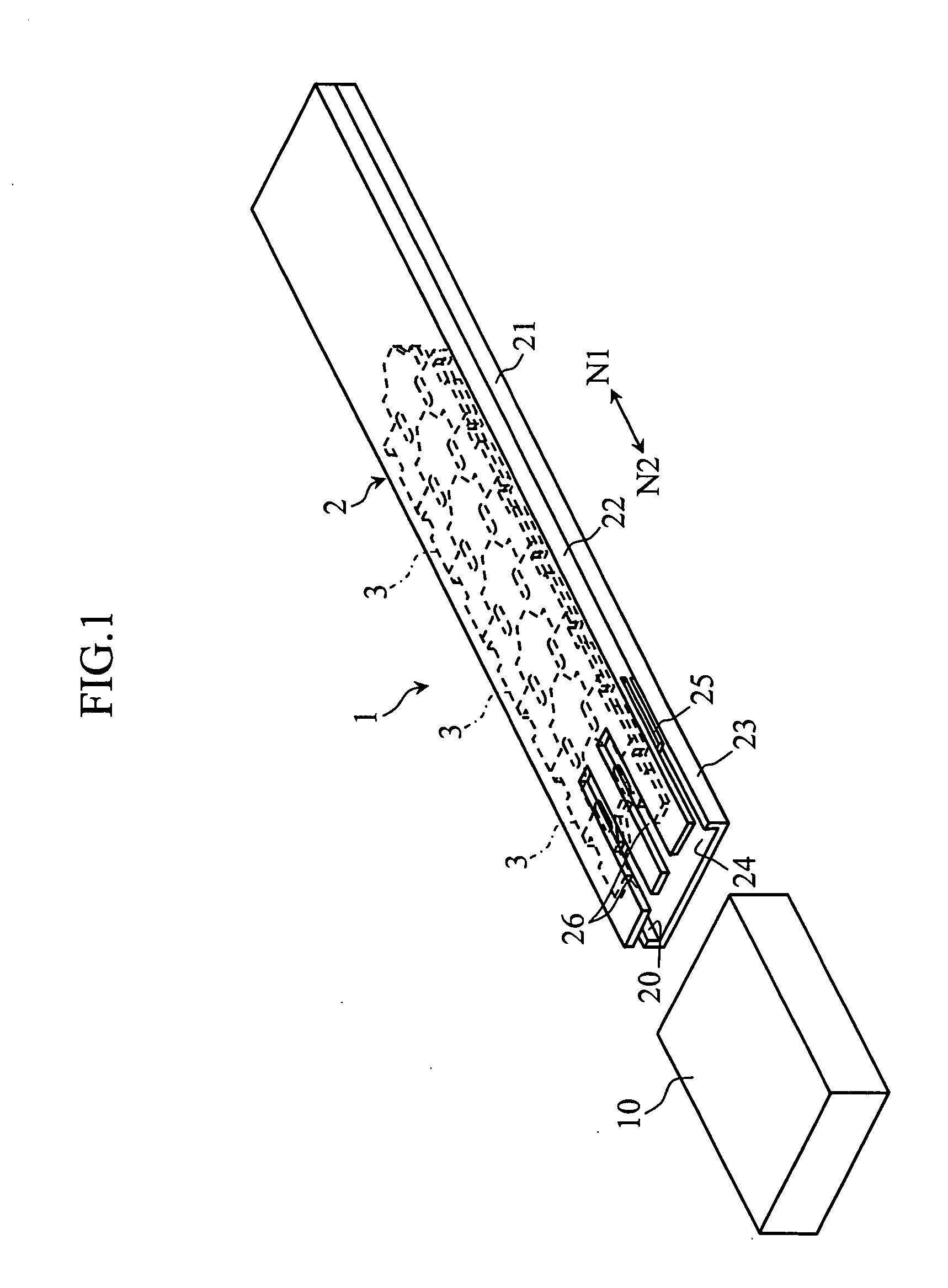
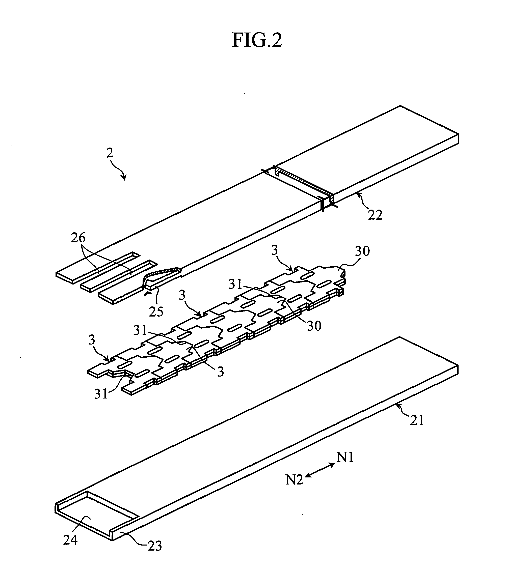
[0055]A cartridge 1 shown in FIGS. 1 and 2 accommodates a plurality of biosensors 3 in a case 2, where the biosensor 3 is taken out one at a time from the plurality of biosensors 3 for use.

[0056]As shown in FIGS. 2 to 5, the biosensor 3 is used to analyze a specific component (e.g., glucose, cholesterol, or lactic acid) in a sample such as blood and urine by being attached to an analyzer 6 (see FIGS. 10A and 10B), to be hereinafter described. The biosensor 3 is adapted to analyze a sample through electrochemical method, and is formed into a plate-shape as a whole. The plurality of biosensors 3 are arranged lined in a longitudinal direction N1, N2 of the case 2 in the cartridge 1. Each biosensor 3 has a projecting portion 30, a recessed portion 31, a pair of engagement projections 32, a pair of engagement holes 33, a pair of through-holes 34, and a pair of cutouts 35.

[0057]The projecting p...


PUM

PropertyMeasurementUnit
thicknessaaaaaaaaaa
oval shapeaaaaaaaaaa
capillary forceaaaaaaaaaa

Abstract

The present invention relates to a cartridge 1 including a plurality of analyzing tools 3 arranged lined in a plane direction and a case 2 for accommodating the plurality of analyzing tools 3, and being configured to take out the analyzing tool 3 one at a time from the case 2. The plurality of analyzing tools 3 further include engagement means 32, 33 for restricting the analyzing tools 3 adjacent to each other in the plane direction and allowing removable attachment in a thickness direction D1, D2 of the analyzing tool 3. The present invention further relates to an analyzer and an analyzing system for analyzing a sample using the cartridge 1.

Description

TECHNICAL FIELD[0001]The present invention relates to a cartridge equipped with a plurality of analyzing tools, and an analyzer for taking out the analyzing tool from the cartridge and analyzing a sample using such an analyzing tool.BACKGROUND ART[0002]An analyzing tool such as a biosensor is used when measuring a specific component in a sample such as blood. The analyzing tool is configured to be disposable, where such an analyzing tool is used by being attached to an analyzer.[0003]The disposable analyzing tool generally has a capillary formed by joining a substrate and a cover by way of a spacer, where a reagent layer is provided in the interior of the capillary. Such an analyzing tool is desirably small in view of material cost, production equipment expense, production equipment installation area, transportation cost, convenience of the user in carrying around, and the like. However, if the analyzing tool is small, operability deteriorates when the user attaches the analyzing to...

Claims


Application Information

Patent Timeline
Patent Type & Authority Applications(United States)
IPC IPC(8): G01N31/22B65D69/00
CPCG01N33/48757Y10T436/203332Y10T436/212G01N35/02G01N1/00G01N27/28G01N27/327
Inventor SATO, YOSHIHARU
Owner ARKRAY INC
Learn More