
Trigger switch

a technology of trigger switch and trigger switch, which is applied in the direction of electric switch, basic electric elements, electric apparatus, etc., can solve the problems of erroneous operation and occurrence of corrosion, and achieve the effect of preventing leakage or erroneous operation, preventing the entry of water from the outside, and preventing corrosion

Active Publication Date: 2010-07-29
MAKITA CORP +1
View PDF4 Cites 2 Cited by
  • Summary
  • Abstract
  • Description
  • Claims
  • Application Information

AI Technical Summary

Benefits of technology

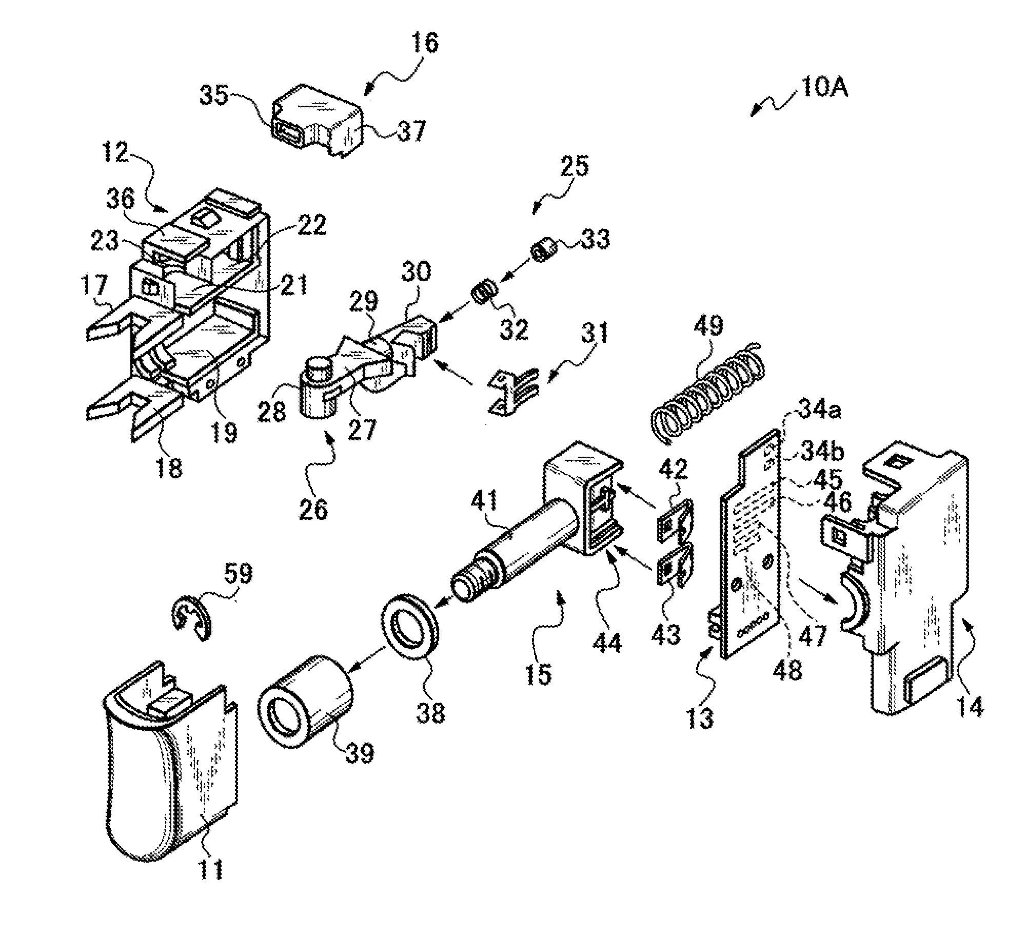
[0011]Accordingly, it is an object of the invention to provide a trigger switch having a switching lever configured to switch the direction of rotation of a motor between a normal rotation and a reverse rotation, in which entry of water which might occur in association with an switching operation is prevented, and leak between contact points is prevented even when water reaches contact elements on a sliding circuit board, whereby occurrence of corrosion is restrained to eliminate the possibility of erroneous operation.
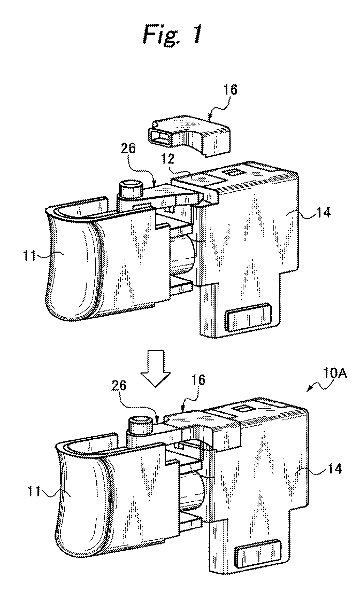
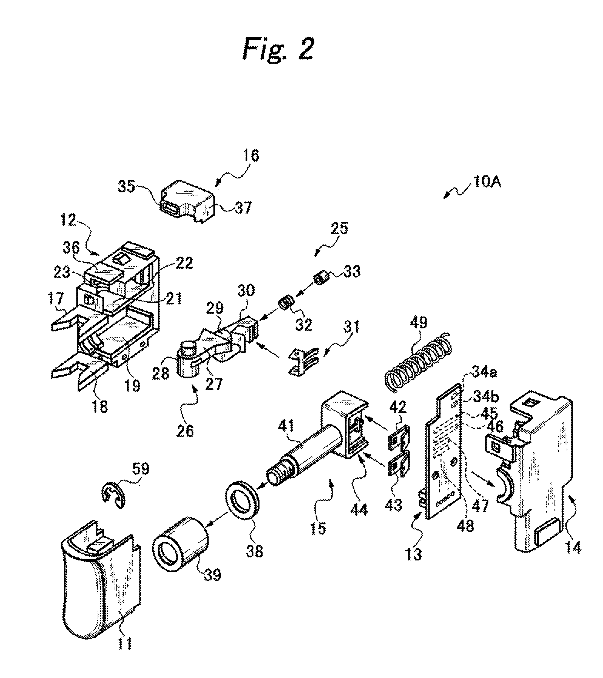
[0012]In order to solve the above-described problems, according to an aspect of the invention, there is provided a trigger switch including: a switching operation unit configured to control the rotation of a motor between a normal rotation and a reverse rotation; a sliding operation unit configured to be coupled to a trigger lever, a case configured to store the switching operation unit and the sliding operation unit; a cover configured to dose an opening surface of the case, the switching operation unit being partly built into an upper position of the case, and including a switching contact strip formed of a conductive metallic member which generates switching signals on a side surface of a rear end portion thereof, and a switching lever having a revolving shaft rotatably provided at a substantially center position, the sliding operation unit being partly build into a lower position of the case, and including a speed control unit having a sliding element which is configured to move in association with the operation of the trigger lever, and a sliding shaft coupled at a rear end to the speed control unit and allows the trigger lever to be mounted on a distal end portion thereof, the cover including a sliding circuit board having contact elements on which the sliding element slides, wherein the case is formed with a speed control unit storage chamber configured to store the speed control unit, a revolving shaft storage chamber configured to store the revolving shaft of the switching lever, and a contact strip member storage chamber provided with continuing from the revolving shaft storage chamber through a shielding member therebetween and configured to store the contact strip member of the switching lever, the revolving shaft storage chamber is formed with a revolving shaft engaging hole configured to allow the revolving shaft to be inserted in an engaged state on an upper portion thereof on the side of the trigger lever, and a waterproof device configured to cover at least a gap between the switching lever and the revolving shaft engaging hole is provided to prevent entry of water therein.
[0018]According to the trigger switch in the invention, problems such as leak or erroneous operation are prevented by rendering waterproof around the revolving shaft of the normal and reverse switching lever which is most subjected to entry of water in terms of structure. In addition, entry of water from the outside is completely prevented by enlarging the range of waterproof to the sliding operation unit that is moved in conjunction with the trigger lever.
[0019]Further, occurrence of corrosion due to the leak between the contact points of the contact elements is restrained even when water is adhered on the contact elements by covering the contact elements disposed on the sliding circuit board with a low-resistance resister. Further, adhesion of water is restrained by forming the slits between the contact elements, so that the leak between the contact points is eliminated, and occurrence of the corrosion is restrained.

Problems solved by technology

However, since any protective measure for entry of water from the outside is not taken at all, there is a problem such that water enters from around the revolving shaft 29 of the switching lever in association with a switching operation of the switching lever, and the entered water is propagated to contact elements disposed on a sliding circuit board, thereby causing an erroneous operation.
There is another problem in the prior art such that the contact element of the sliding circuit board has a configuration in which electrodes or upper portions of the electrodes are coated with resister for allowing movable contact strips (rotation control sliding element, switch sliding element) to slide thereon, and hence the entry of water causes leak between the electrodes, which accelerates occurrence of corrosion, thereby causing the erroneous operation.

Method used


Image

  • Trigger switch
  • Trigger switch
  • Trigger switch

Examples


third embodiment

[0047]FIGS. 6 and 7 show a trigger switch 10C which employs a waterproof packing 16A which prevent the entry of water not only from the portion of the switching lever 26, but also from the portion of the sliding operation unit 15 which is slid by the operation of the trigger lever 11. In other words, the waterproof packing 16A is formed integrally with a lever engaging portion 52 configured to allow penetration of the arm member of the switching lever 26 therethrough and cover the same, a guide engaging portion 53 configured to allow penetration of the upper lever guide member 17 therethrough and cover the same, and a sliding operation packing 54 configured to allow penetration of the sliding shaft 41 therethrough and serve also as an external packing. With the waterproof packing 16A, as shown in FIG. 7, since the substantially entire parts of the cover 14 and the case 12 are covered, a joint portion between the case 12 and the cover 14 is covered in addition to the prevention of e...

fifth embodiment

[0049]FIG. 10 shows the sliding circuit board 13 in a trigger switch according to a The contact elements 45, 46, 47, and 48 provided on the sliding circuit board 13 are coated with a low-resistance resistance film 57, for example, a film of the conductive member formed of carbon. In this configuration, adhesion of incoming water is prevented and phenomena occurring in association with the adhesion of water such as electrolysis are restrained.

[0050]FIG. 11 shows the sliding circuit board 13 in the trigger switch according to a sixth embodiment. The sliding circuit board 13 in the sixth embodiment is formed with slits 58 between the switching contact elements 34a and 34b, between the contact elements 45 and 46, and between the contact elements 47 and 48, respectively. In this configuration, since incoming water does not reach the contact elements, the phenomenon such as the electrolysis is restrained. Consequently, leak and the like are eliminated and occurrence of corrosion is restr...


PUM


Abstract

In a trigger switch having a normal and reverse switching lever configured to switch the direction of rotation of a motor, a case is formed with a speed control unit storage chamber for storing a speed control unit, a revolving shaft storage chamber for storing a revolving shaft of the switching lever and a contact strip member storage chamber with continuing from the revolving shaft storage chamber through a shielding member therebetween for storing contact strip member of the switching lever, the revolving shaft storage chamber is formed with a revolving shaft engaging hole configured to allow the revolving shaft to be inserted in an engaged state on an upper portion thereof on the side of the trigger lever, and a waterproof device for covering at least a gap between the switching lever and the revolving shaft engaging hole is provided to prevent entry of water therein.

Description

BACKGROUND OF THE INVENTION[0001]1. Field of the Invention[0002]The present invention relates to a trigger switch having a normal and reverse switching lever used in a brushless motor-mounted power tool or the like and, more specifically, to a trigger switch having waterproof, leak-proof, and corrosion-proof structures.[0003]2. Prior Art[0004]A “trigger switch” described in JP-A-2009-054540 for example is known as a trigger switch having a normal and reverse switching lever in the prior art. As shown in FIGS. 12, 13, and 14, the trigger switch has a configuration including a sliding operation unit 15 having a sliding contact point mechanism integrated in the interior of a main body formed into a box shape, and configured to transmit a sliding operation from an external trigger lever 11, and also including a case 12 opening on a side surface, a cover 14 configured to close an opening surface on the side surface of the case 12 and provided with a sliding circuit board 13 mounted on an...

Claims


Application Information

Patent Timeline
IPC IPC(8): H01H13/02
CPCH01H9/04H01H9/063
Inventor INAGAKI, ISAONISHIKIMI, JUNICHITOMONAGA, AKIRA
Owner MAKITA CORP
Learn More