
Electromagnetic relay

a technology of electromagnetic relays and junction terminals, applied in electromagnetic relays, electrical apparatus, and electromagnetical relay details, etc., can solve problems such as difficulty in connecting junction terminals b>123, and achieve the effect of high rate and easy assembly

Inactive Publication Date: 2010-07-22
GOOD SKY ELECTRIC
View PDF21 Cites 15 Cited by
  • Summary
  • Abstract
  • Description
  • Claims
  • Application Information

AI Technical Summary

Benefits of technology

[0007]Therefore, an object of the present invention is to provide an electromagnetic relay that is easy to assemble and that can be fabricated at a high rate.

Problems solved by technology

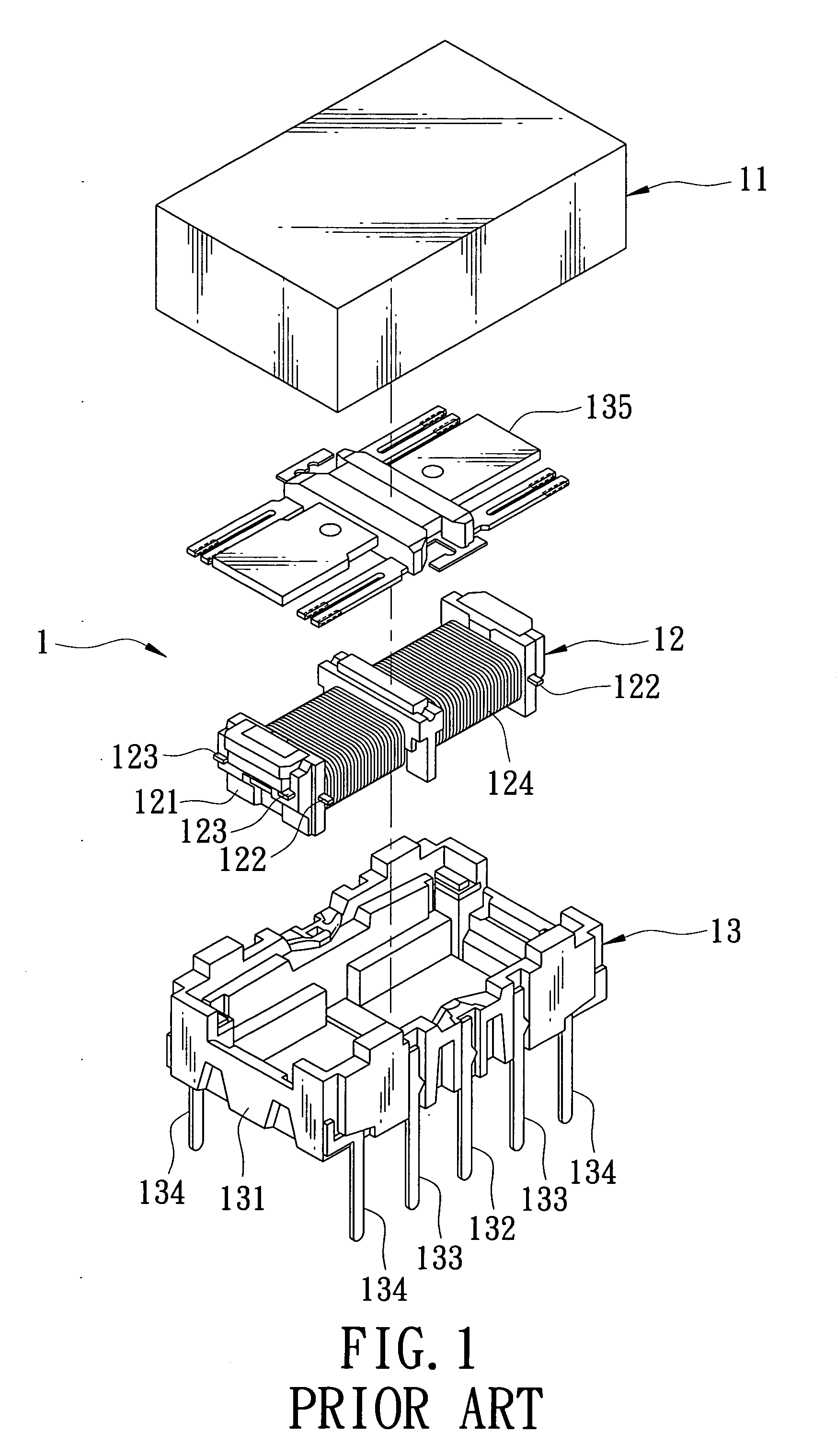
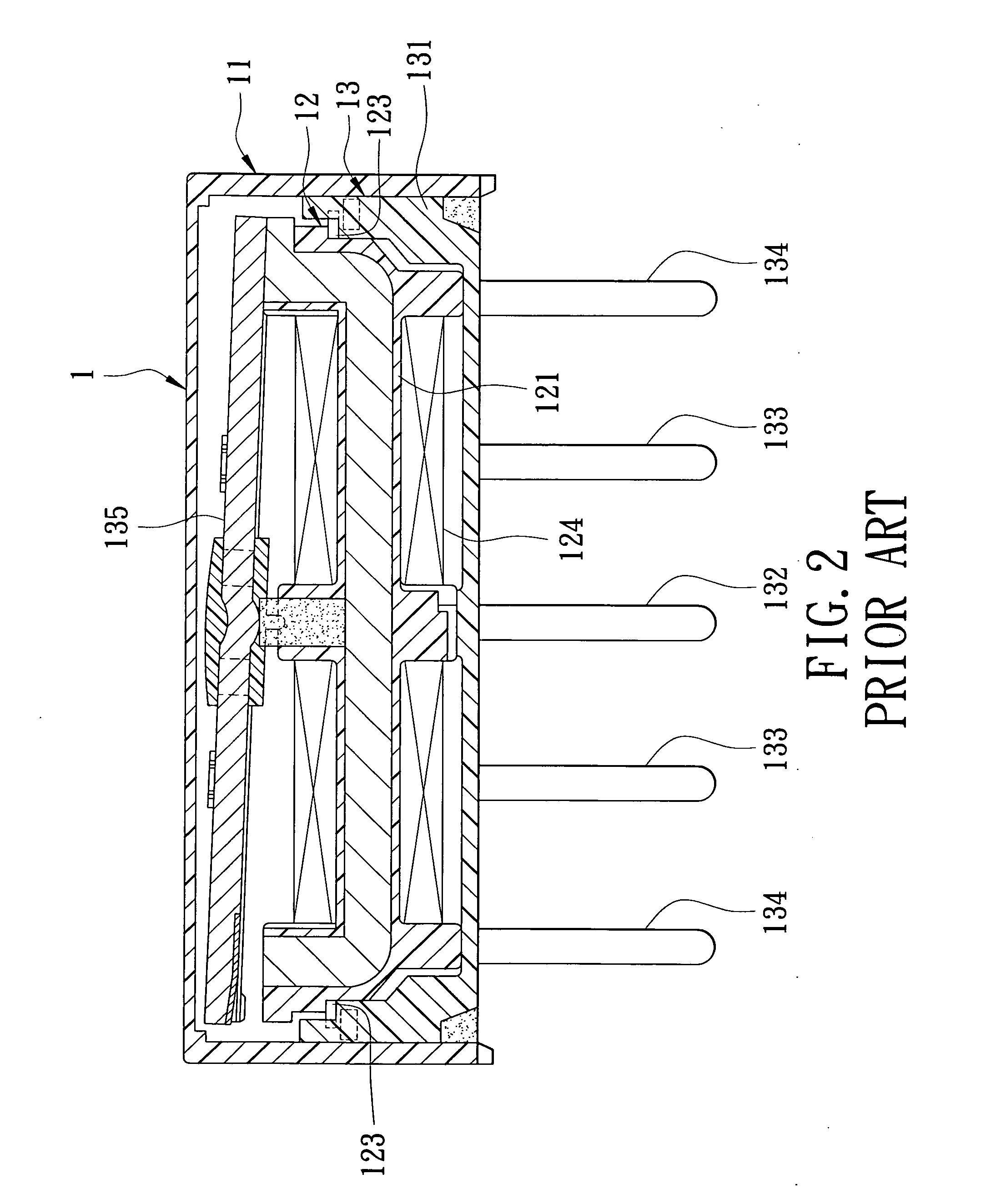
Moreover, since there is no mechanism for fixing the electromagnet block 12 in the base body 131, it is difficult to connect the junction terminals 123 accurately to the coil terminals 134 during assembly.

Method used


Image

  • Electromagnetic relay
  • Electromagnetic relay
  • Electromagnetic relay

Examples


Embodiment Construction

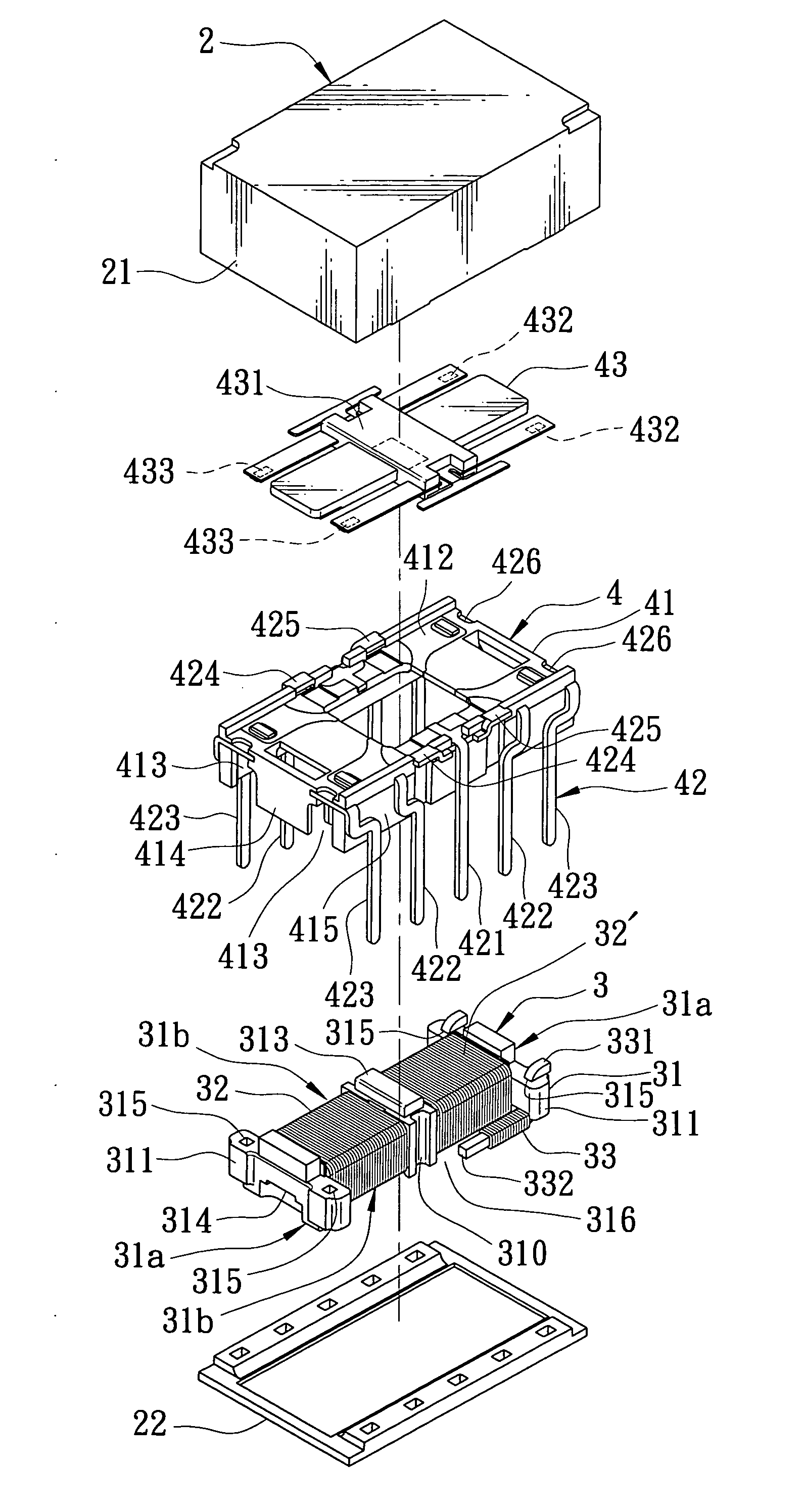
[0022]Referring to FIGS. 3 and 4, an electromagnetic relay of the preferred embodiment of this invention includes a casing 2 and a relay core member including an electromagnetic unit 3 and a terminal unit 4.

[0023]The casing 2 includes an upper casing body 21 and a bottom casing body 22 that are connected with each other by press fitting.

[0024]The electromagnetic unit 3 is adapted for generating an electromagnetic field, and includes a spool frame set 31 having a pair of opposite first sides (31a) and a pair of opposite second sides (31b), a coil unit 32 being wound on the spool frame set 31 and including at least one coil 32′, and a pair of coil winding pins 33. The spool frame set 31 includes a spool frame 310 wound with the coil unit 32, a pair of mounting frames 311, an iron core 312 attached fixedly to the spool frame 310, and a permanent magnet 313 inserted into the spool frame 310 and disposed on a middle portion of the iron core 312. Each of the mounting frames 311 is dispose...


PUM


Abstract

An electromagnetic relay includes a casing, and a relay core member sealed in the casing and including an electromagnetic unit and a terminal unit. The electromagnetic unit includes a spool frame set having an engagement portion, a coil unit wound on the spool frame set, and a pair of coil winding pins. Each of the coil winding pins has a conductive portion exposed from one of opposite first sides of the spool frame set, and a coil winding portion extending along one of opposite second sides of the spool frame set. The terminal unit includes an engaging block having an engagement portion connected to the engagement portion of the spool frame set for preventing separation of the terminal unit from the electromagnetic unit, a terminal set, and an armature component.

Description

BACKGROUND OF THE INVENTION[0001]1. Field of the Invention[0002]The present invention relates to an electromagnetic relay, more particularly to an electromagnetic relay including an armature component supported pivotally at a middle portion thereof.[0003]2. Description of the Related Art[0004]Referring to FIGS. 1 and 2, U.S. Pat. No. 4,881,053 discloses an electromagnetic relay 1 including a casing 11, an electromagnet block 12 and a base 13 sealed in the casing 11, and an armature block 135. The electromagnet block 12 includes a spool 121, two pairs of junction terminals 123 having coil winding portions 122 exposed from opposite longitudinal sides of the spool 121, and coils 124 wound on the spool 121. Each of the coils 124 has one end that is to be wound on one of the coil winding portions 122 of the corresponding pair of the junction terminals 123, and the other end that is to be wound on the other one of the coil winding portions 122 of the corresponding pair of the junction ter...

Claims


Application Information

Patent Timeline
Patent Type & Authority Applications(United States)
IPC IPC(8): H01H45/00H01H45/02
CPCH01H50/043H01H50/14H01H51/229
Inventor KUO, MING-CHANG
Owner GOOD SKY ELECTRIC
Learn More