
Water collection device

a technology of water collection device and water collection chamber, which is applied in the direction of defrosting, heating type, domestic cooling apparatus, etc., can solve the problems of structural damage to foundations and walls, moisture also has a tendency to attract termites, etc., and achieves the effects of preventing mold growth, preventing mold growth, and preventing mold growth

Inactive Publication Date: 2010-07-22
GAVAN WILLIAM J
View PDF19 Cites 11 Cited by
  • Summary
  • Abstract
  • Description
  • Claims
  • Application Information

AI Technical Summary

Benefits of technology

[0011]It is, therefore, one of the primary objects of the present invention to provide an easy to use water collection device to catch water that condenses on and drips from an air conditioner. Another object of the present invention is to provide a device for preventing water from dripping from an air conditioning unit and settling at the base of a home, such device thereby preventing mold growth, structural damage, insect infestation, pest problems, moisture problems, and the like.
[0012]Still another object of the present invention is to provide an easy to use device for collecting otherwise wasted water which can then be used to water trees, plants, grass, gardens, and the like thereby conserving natural resources.
[0013]Yet another object of the present invention is to provide a condensation catching device to collect water which condenses from use of an air conditioning unit for use in watering plants, trees, a lawn, etc. thereby decreasing a user's water expenses.

Problems solved by technology

While it is useful to control the temperature of the interior of such structures, when in use, air conditioners produce condensation and water run off which drips and runs from such air conditioners onto the ground at the base of such structures where it may cause moisture buildup ultimately resulting in structural damage to foundations and walls.
Moreover, such moisture also has a tendency to attract termites.

Method used


Image

  • Water collection device
  • Water collection device
  • Water collection device

Examples


Embodiment Construction

, particularly, when such description is taken in conjunction with the attached drawing figures and with the appended claims.

BRIEF DESCRIPTION OF THE DRAWINGS

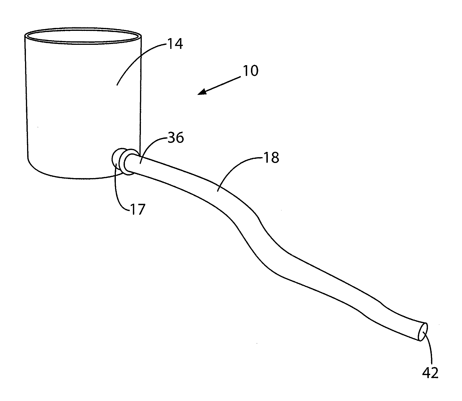
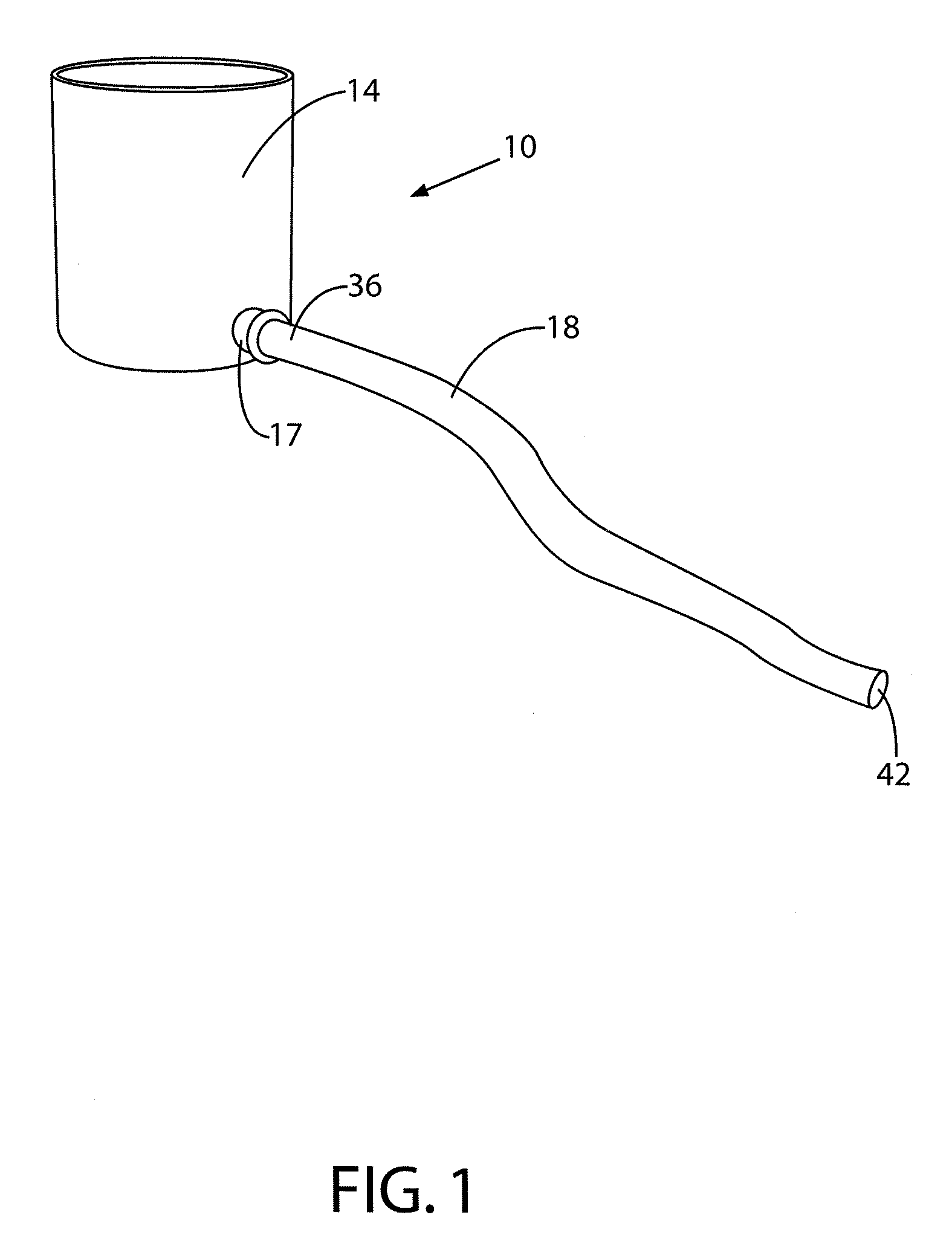
[0015]FIG. 1 is a partial perspective view of the invention according to one embodiment.

[0016]FIG. 2 is a partial perspective view of the invention according to one embodiment.

[0017]FIG. 3 is a partial perspective view of the invention according to one embodiment.

[0018]FIG. 4 is a partial perspective view of the invention according to one embodiment.

[0019]FIG. 5 is a partial cut away view of the invention according to one embodiment of the invention.

BRIEF DESCRIPTION OF A PRESENTLY PREFERRED AND VARIOUS ALTERNATIVE EMBODIMENTS OF THE INVENTION

[0020]Prior to proceeding to the more detailed description of the present invention it should be noted that, for the sake of clarity and understanding, identical components which have identical functions have been identified with identical reference numerals throughout the several views il...


PUM


Abstract

A water collection device for collecting water at least one of condensing, dripping, flowing, running, and a combination thereof from an exhaust portion of an air conditioner includes a housing having an open ended top portion for placement at least one of beneath an exhaust portion of such air conditioner, closely adjacent an exhaust portion of such air conditioner, and a combination thereof. Water enters such housing through such top portion for collection. An aperture is disposed through at least one of a side wall, a bottom wall and a combination thereof of such housing. An attachment mechanism is operably connected to such aperture. A hose is releasably attachable at a first end thereof to such housing via such attachment mechanism and receives collected water flowing through such aperture into such hose. Such water exits a second end of such hose for dispersal to a predetermined area.

Description

CROSS REFERENCE TO RELATED APPLICATION[0001]This patent application is related to and claims priority from U.S. Provisional Patent Application Ser. No. 61 / 145,167 filed Jan. 16, 2009.FIELD OF THE INVENTION[0002]The present invention relates, in general, to water collection devices and, more particularly, this invention relates to a device for use in collecting water which condenses on air conditioning units and from the exhaust portions of such air conditioning units.BACKGROUND OF THE INVENTION[0003]Prior to the conception and development of the present invention, air conditioners, as are generally well known in the prior art, have been used to keep houses and other buildings cool in uncomfortably warm climates. While it is useful to control the temperature of the interior of such structures, when in use, air conditioners produce condensation and water run off which drips and runs from such air conditioners onto the ground at the base of such structures where it may cause moisture b...

Claims


Application Information

Patent Timeline
IPC IPC(8): F25D21/14
CPCF24F13/222
Inventor GAVAN, WILLIAM J.
Owner GAVAN WILLIAM J
Learn More