
Air flow control damper with linear performance characteristics comprising an air foil control blade and inner annular orifice

a technology of air foil control and linear performance characteristics, which is applied in the direction of lighting and heating apparatus, ventilation systems, heating types, etc., can solve the problems of unstable performance characteristics, low flow, and low performan

Inactive Publication Date: 2010-07-15
COWARD CHARLES W
View PDF8 Cites 26 Cited by
  • Summary
  • Abstract
  • Description
  • Claims
  • Application Information

AI Technical Summary

Problems solved by technology

This ability to maintain constant pressure differences is often a design challenge in research laboratories where both space occupancy and hood usage change dramatically during a 24 hr period.
There are three currently popular air flow damper designs; one is with a flat damper blade with a low pressure drop but its performance is not linear, an airfoil damper with a series of inflatable airfoil blades but operable only by compressed air and a venturi damper but with very high pressure drop.
Often air flow control dampers are required to accurately and repetitively control very low flow rates.
This restriction often called an impact loss which causes a much lower flow than is actually possible if the air did not impact the casing as well as causing an unstable (non constantly rising) pressure volume curve.
If the blade surface is flat the air discharging from the blade and impacting the inner surface of the casing will collapse behind the blades into the area of negative pressure behind the blade contributing to the unstable performance characteristics.
George (U.S. Pat. No. 6,991,177) teaches an extended turndown by means of separate blades in separate parallel channels with a resulting more complex construction.
George does not teach the need for linear performance characteristics required for maintaining constant offsets and space pressures in critical spaces when using a VAV system design.
McCabe et al (2002 / 0175307) and Moore et al (U.S. Pat. No. 6,557,826) also disclose multi blade dampers but do not teach the use of an inner orifice or the need for linear performance without hystersis.
The single blade is the least expensive shape to manufacture but does not equally modulate the upper half of the airstream as well as the lower half.

Method used


Image

  • Air flow control damper with linear performance characteristics comprising an air foil control blade and inner annular orifice
  • Air flow control damper with linear performance characteristics comprising an air foil control blade and inner annular orifice
  • Air flow control damper with linear performance characteristics comprising an air foil control blade and inner annular orifice

Examples


Embodiment Construction

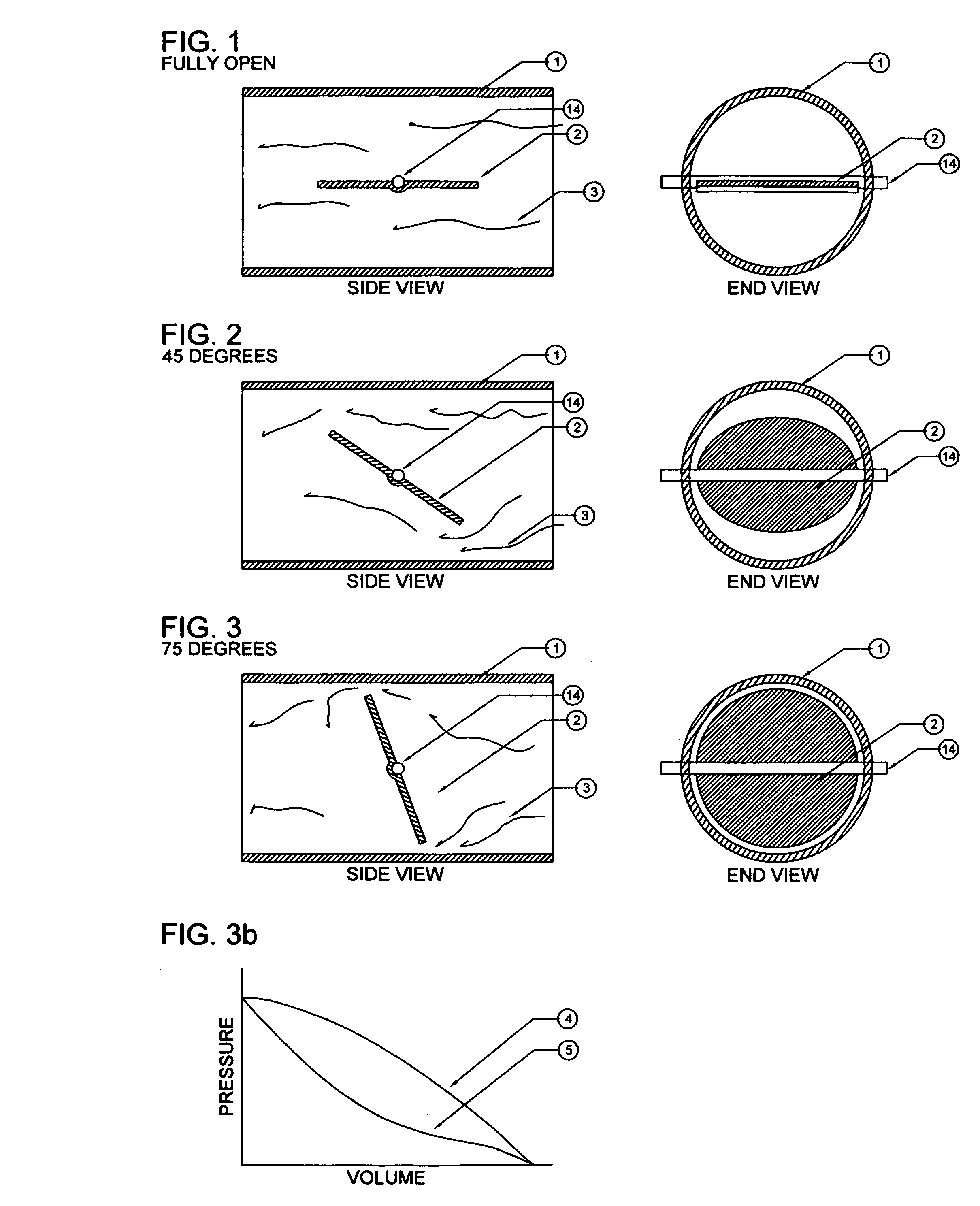
[0021]FIG. 1 shows a side view of an ordinary control damper composed of an outer casing (1) with a flat air control blade (2) and without a internal orifice. Also shown is the flat blade a primarily open position. Again the airflow patterns (3) are shown deflected by the blade most of which pass through the damper parallel to the axis of the damper and the remainder will impact the inner surface of the outer casing shown. In this instance there is a minimal amount of the air flow impacting the inner surface of the outer casing (1).

[0022]FIG. 2 shows that same ordinary control damper with an outer casing (1) with the flat control blade (2) at a mid point position approximately 45 deg to the axis of the casing. Also shown are air flow patterns (3) deflected by the blade (2) most of which pass through the damper at about a 45 deg angle to the axis of the damper and the remainder will impact the inner surface of the outer casing (1) with some force and loss of energy prior to passing t...


PUM


Abstract

An air flow control damper consisting of either a tubular or rectangular casing, an internal annular orifice and within the orifice a rotatable circular or rectangular blade with an air foil profile. The blade may be either single or multi-part. The air flow control blade is designed to rotate on a shaft from an open position to a closed position modulating the air flowing through the casing. This damper exhibits a very low pressure drop—important for energy conservation—and a linear hystersis free performance curve—important when maintaining pressures in critical spaces.

Description

FIELD OF INVENTION [0001]This invention relates to an air flow control damper which is capable of stable performance curve as well as linear and hystersis free control of the air flowing to or from a space. A very low pressure drop is desirable where compliance with current energy codes is desired. Minimal noise and suitability for DDC control are other attributes.BACKGROUND OF THE INVENTION [0002]Critical spaces need very close pressure and volume control to maintain the design environmental conditions. These spaces require special pressures—positive or negative to the surrounding spaces. Examples are Research Laboratories which are normally negative to the surrounding spaces to contain odors and fumes. Or, as an alternative, clean spaces may require a positive pressure which prevents contaminated air from entering the clean space. Additionally some spaces are designed for varying flow rates between maximum and minimum low flow rates (VAV) and must maintain the same space pressures...

Claims


Application Information

Patent Timeline
IPC IPC(8): F24F13/10
CPCF24F11/04F24F11/047F24F2013/242F24F2011/0038F24F13/142F24F2110/30F24F11/74F24F11/75
Inventor COWARD, CHARLES W.
Owner COWARD CHARLES W
Learn More