
Projecting lens and projecting apparatus using the same

a projecting apparatus and wide angle technology, applied in the field of projecting lenses, can solve the problem that the size of the projecting frame of the projecting apparatus is subject to the structural, and achieve the effect of convenient assembly

Active Publication Date: 2010-07-08
QUISDA CORP
View PDF2 Cites 26 Cited by
  • Summary
  • Abstract
  • Description
  • Claims
  • Application Information

AI Technical Summary

Benefits of technology

[0006]The invention is directed to a projecting lens and a projecting apparatus using the same, which have the advantages of super wide angle and easy assembly.

Problems solved by technology

However, the size of the projecting frame of the projecting apparatus is subject to the structural design of the projecting lens.
Conventionally, the design of the wide-angle projecting lens is based on first imaging principle, which would normally lead to the problems such as the front lens group being too big, and require other elements such as the reflective mirror or the lens with specific lens surface.

Method used


Image

  • Projecting lens and projecting apparatus using the same
  • Projecting lens and projecting apparatus using the same
  • Projecting lens and projecting apparatus using the same

Examples


Embodiment Construction

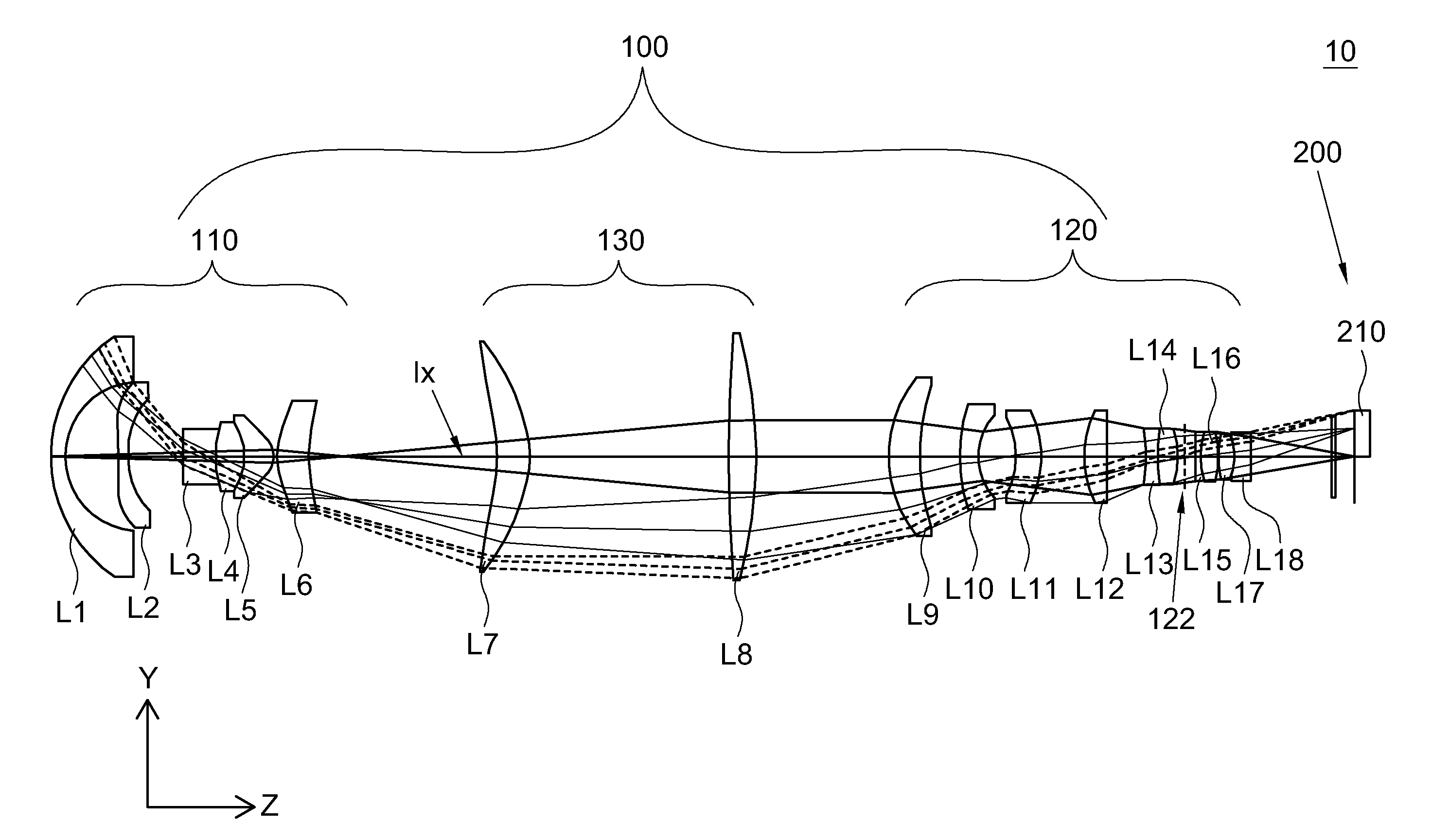
[0014]Referring to FIG. 1, a projecting apparatus according to a preferred embodiment of the invention is shown. The projecting apparatus 10 includes a projecting lens 100 and an image generating device 200. The image generating device 200 has a light valve 210 for providing an image projecting light to the projecting lens 100, such as but not limited to a digital micro-mirror device (DMD), and any device capable of achieving the above function will be adopted. The projecting lens 100 includes a first lens group 110 and a second lens group 120, wherein the second lens group 120 is disposed between the first lens group 110 and the light valve 210. The first lens group 110 has an imaging optical axis Ix and a first effective refractive power. The second lens group 120 has a second effective refractive power. As indicated in FIG. 1, the projecting lens 100 further includes a third lens group 130 which is disposed between the first lens group 110 and the second lens group 120 and has a ...


PUM


Abstract

A projecting lens for projecting a light of an image generating device onto a screen is provided. The image generating device has a light valve. The projecting lens includes a first lens group and a second lens group. The first lens group has an imaging optical axis and a first effective refractive power. The second lens group has a second effective refractive power, and is disposed between the first lens group and the light valve. The light projected from the light valve to the second lens group generates an intermediate image, which is focused on the screen via the first lens group to form an image. A center of the image and a center of the light valve are located on the same side of the optical axis, and a center of the intermediate image is located on the other side of the optical axis.

Description

[0001]This application claims the benefit of Taiwan application Serial No. 98100076, filed Jan. 5, 2009, the subject matter of which is incorporated herein by reference.BACKGROUND OF THE INVENTION[0002]1. Field of the Invention[0003]The invention relates in general to a projecting lens, and more particularly to a projecting lens with wide angle and a projecting apparatus using the same.[0004]2. Description of the Related Art[0005]To project an image at a big space such as a big conference room or a hall, a bigger projecting frame is required. However, the size of the projecting frame of the projecting apparatus is subject to the structural design of the projecting lens. Thus, a wide-angle projecting lens is commonly used in the projecting apparatus. Conventionally, the design of the wide-angle projecting lens is based on first imaging principle, which would normally lead to the problems such as the front lens group being too big, and require other elements such as the reflective mir...

Claims


Application Information

Patent Timeline
IPC IPC(8): G02B27/18
CPCG02B13/16
Inventor LIN, MING-KUENWU, TSUNG-HSUN
Owner QUISDA CORP
Learn More