
Apparatus and Method for Providing Antenna Beamforming

a technology of antenna beamforming and antenna beam, which is applied in the field of multi-antenna systems, can solve the problems of loss of radiated energy, large energy directed away from the intended recipient,

Inactive Publication Date: 2010-07-01
GOOGLE TECH HLDG LLC
View PDF7 Cites 72 Cited by
  • Summary
  • Abstract
  • Description
  • Claims
  • Application Information

AI Technical Summary

Benefits of technology

The present invention provides a method and device for beamforming using multiple antennas. The device detects user interaction and device proximity to other objects, and computes a phase adjustment to enhance the received energy at the intended destination. The phase adjustment is applied to the antennas, and a signal is transmitted to the destination. The invention also includes a receiver for detecting signals from outside the device and identifying the direction of the intended destination. The technical effects of the invention include improved signal quality and more efficient communication.

Problems solved by technology

Furthermore, much of the energy which is directed away from the intended recipient in turn contributes to the noise experienced by other wireless communication devices.
This results in a loss of radiated energy, which is precluded from having being received as intended, even though it might have been appropriately directed toward the intended recipient.

Method used


Image

  • Apparatus and Method for Providing Antenna Beamforming
  • Apparatus and Method for Providing Antenna Beamforming
  • Apparatus and Method for Providing Antenna Beamforming

Examples


Embodiment Construction

)

[0017]While the present invention is susceptible of embodiment in various forms, there is shown in the drawings and will hereinafter be described presently preferred embodiments with the understanding that the present disclosure is to be considered an exemplification of the invention and is not intended to limit the invention to the specific embodiments illustrated.

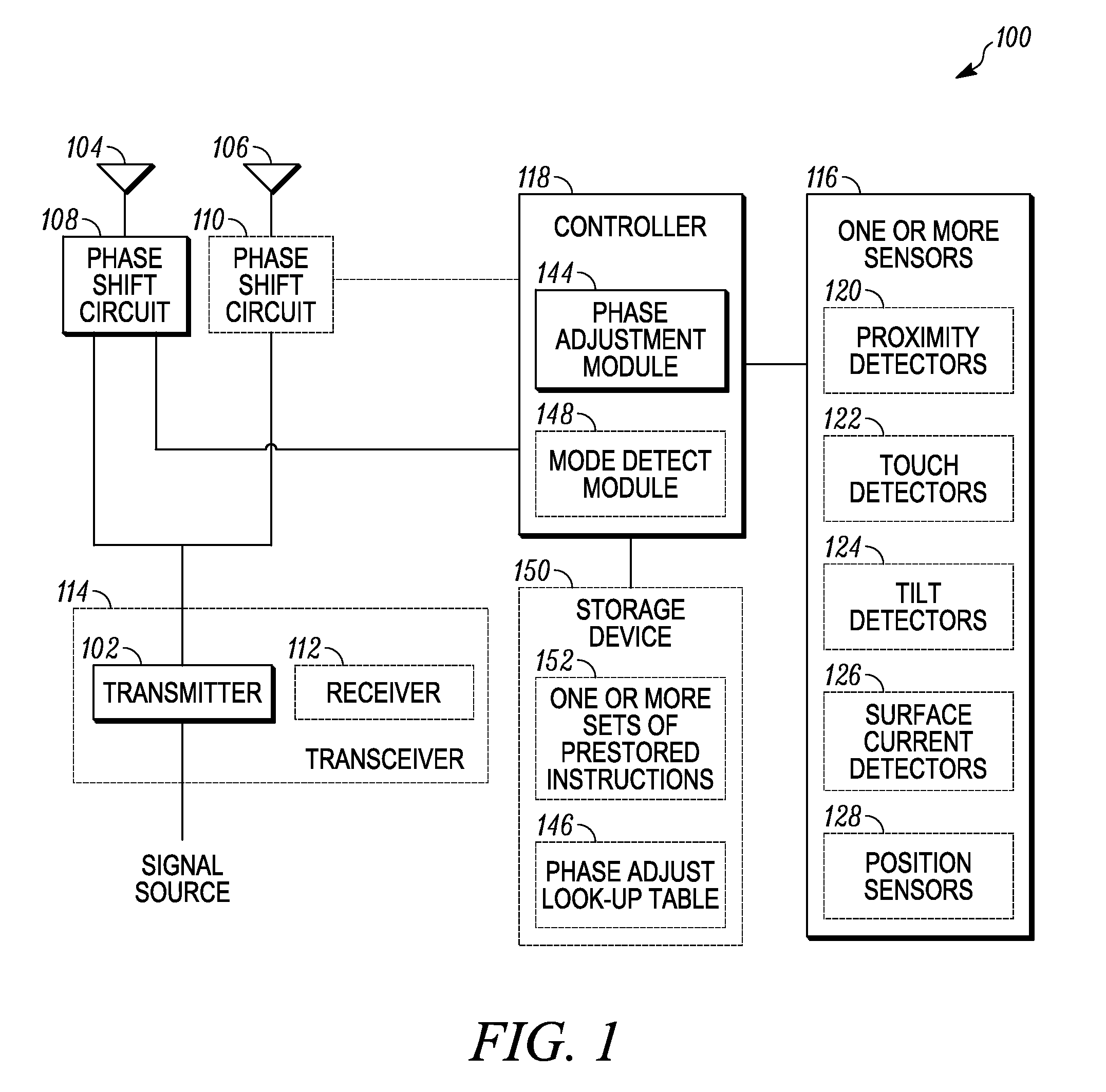
[0018]FIG. 1 illustrates a block diagram of wireless communication device 100 for providing antenna beamforming, in connection with transmitting a signal, in accordance with at least one embodiment of the present invention. Beamforming often involves the use of a plurality of antennas, which transmit a similar signal, which in some directions will constructively add, and in other directions will destructively interfere. As such, there are directions of transmissions, which in turn will have varying amounts of transmitted energy, with some directions containing more energy and other areas containing less energy, depending...


PUM


Abstract

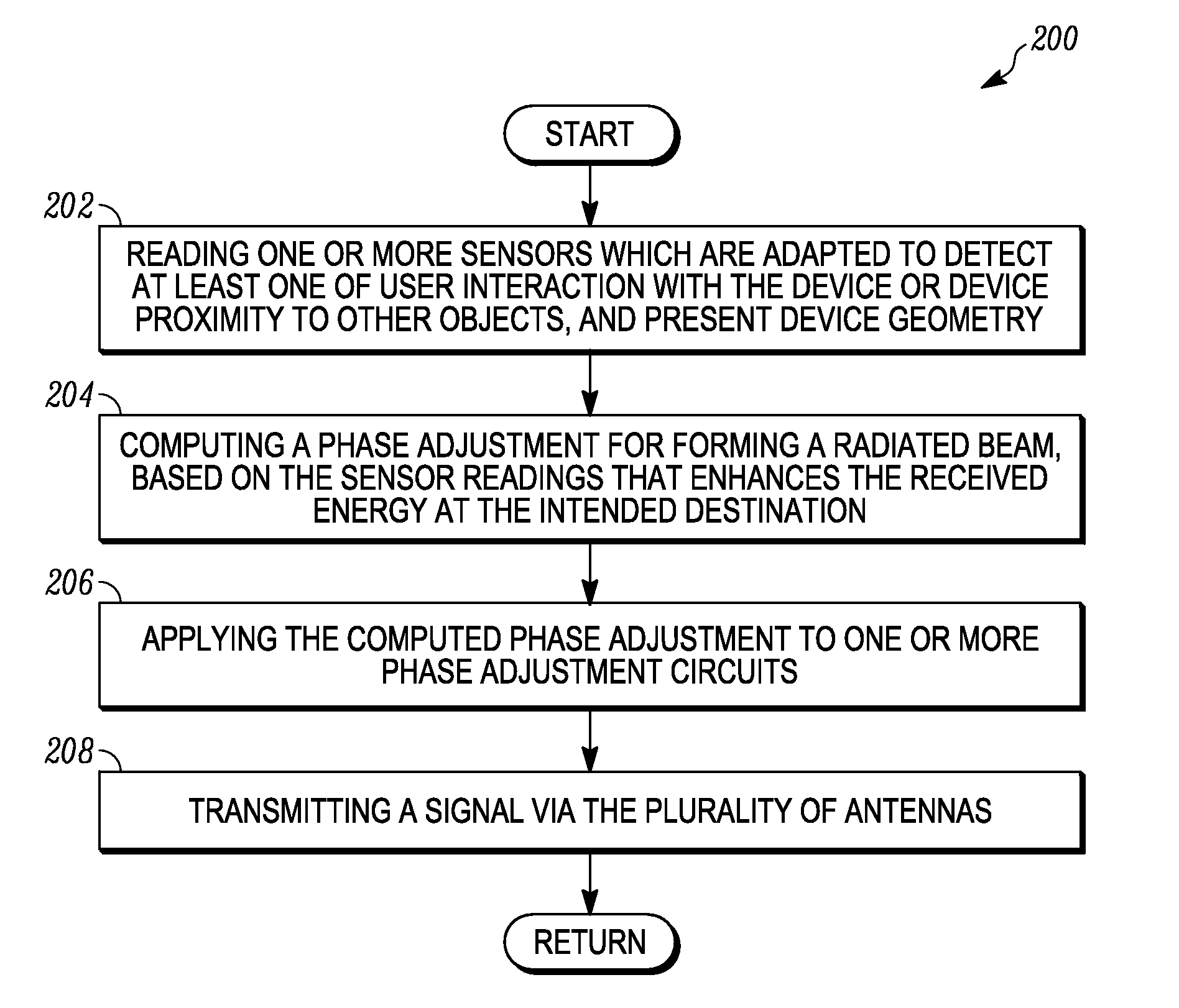
The present invention provides a device and a method in a device having a plurality of antennas for providing beamforming. The method includes reading one or more sensors, which are adapted to detect at least one of user interaction with the device or device proximity to other objects, and present device geometry. A phase adjustment is then computed in a controller for forming a radiated beam, based upon the readings of the one or more sensors, that enhances the received energy at an intended destination. The computed phase adjustment is then applied to one or more phase adjustment circuits, respectively coupled to at least some of the plurality of antennas. A signal is then transmitted by a transmitter to the intended destination via at least some of the plurality of antennas.

Description

FIELD OF THE INVENTION[0001]The present invention relates generally to a multiple antenna system for transmitting a signal, and more particularly, to using the multiple antennas to steer the radiated energy jointly produced by the multiple antennas.BACKGROUND OF THE INVENTION[0002]There is a general trend in connection with electronic products for features and performance to become better over time. In some instances, higher performance is driven by more stringent regulations. In other instances, the increase in performance is the result of natural competition between products in the market place, which are continually trying to boost performance to attract new buyers, and / or a larger percentage of the buyers. This results in electronic manufactures which generally are continually looking for ways to boost performance.[0003]In the case of portable wireless communication devices, battery life is one such factor that has some traction with the consumer in influencing purchasing decisi...

Claims


Application Information

Patent Timeline
Patent Type & Authority Applications(United States)
IPC IPC(8): H04B1/38H04B1/02
CPCH04B7/0617H04B17/27
Inventor SZINI, ISTVAN
Owner GOOGLE TECH HLDG LLC
Learn More