Universal Surgical Plate with 30 Degree Compression Angle

Inactive Publication Date: 2010-06-17
VETERINARY IMPLANTS DIRECT
View PDF33 Cites 16 Cited by
  • Summary
  • Abstract
  • Description
  • Claims
  • Application Information

AI Technical Summary

Benefits of technology

[0010]Tibial Plateau Leveling Osteotomy (TPLO) is a well known orthopedic technique for treatment of cranial cruciate ligament rupture in canines, as shown and described, for example, in Slocum, U.S. Pat. No. 5,304,180. During a TPLO procedure, the slope of the tibial plateau is reduced causing tibial forces on the stifle joint to shift from the cranial toward the caudal end with a greater reliance on the caudal cruciate ligament for stability. The illustrated embodiment of the invention is directed to a new bone fixation plate to be used in canine tibial plateau leveling osteotomy surgical procedures and difficult fracture repairs where the unique shape of the plate is desired. During a TPLO procedure, the improved bone fixation plate promotes fastening of the bone sections resulting from an optimal centered osteotomy. With a centered osteotomy, the long axis of the tibia remains in the same position, and the surgeon may accurately achieve the desired post operative tibial plateau angle to counter act the cranial tibial thrust. Many anatomical changes are avoided with the centered osteotomy.
[0012]The design of the current surgical plate of the illustrated embodiment allows it to also be placed against assisting jig pins for improved positioning and a better fitting on a smaller proximal fragment that may be present with smaller breeds of canines. The contour of the implant is tailored to suit the profile of the underlying bone. The placement of the staggered apertures defined within the plate improves compression of the osteotomy. The plate has six holes or apertures defined in it to allow the use of orthopedic screws to secure the plate over the osteotomy and to create the compression forces. Forward compression is supported at a 30 degree compression angle through a selected one of two symmetrically defined drive apertures in the plate. The position and number of drive apertures optimizes the fastening of the plate to the underlying bone. The drive and anchor apertures in the plate are recessed to accommodate conventional cortical and cancellous orthopedic screws.
[0014]Furthermore, the plate has four recessed notches on the underside of the plate to provide minimal circulatory compromise to the underlying bone.
[0033]Finally, in another embodiment, the method further comprises reducing the surface contact between the surgical plate and underlying by means of a plurality of notches defined into the reverse side of the body portion.

Problems solved by technology

When the cranial cruciate ligament of an animal such as a canine ruptures, the stifle joint of the animal becomes unstable and causes a decrease in mobility and an increase in arthritis.
However while many of these plates are not without their various degrees of success, several limitations or drawbacks have been found over time which severely limit their use.
Although there have been attempts with some success to perform the TPLO procedure with no specific implants, there is as yet to date no way to provide the desired compression angels for a balanced osteotomy stabilization while the same plate is used on either left or right tibias.
During proximal fragment shift “rock back,” the cranial end of the proximal tibia and the tibial crest becomes unsupported from losing contact of the now caudally displaced proximal fragment, resulting in a possible tibial crest fracture.
Complications such as proximal fragment destabilization or tibial crest fracture could lead to a catastrophic failure of the procedure.
The large body mass requires strong plates and larger screws to be installed while the available bone is limited in size to accommodate the stronger implants.
Finally, most of the TPLO plates found in the prior art can only be used for TPLO procedures or in some proximal tibia fractures.
There as of now no universal surgical bone plate that may also accommodate other fracture repairs such as an ilial fracture where a space conserving shape and a series of preset compression angles are desired.

Method used


Image

  • Universal Surgical Plate with 30 Degree Compression Angle
  • Universal Surgical Plate with 30 Degree Compression Angle
  • Universal Surgical Plate with 30 Degree Compression Angle

Examples


Embodiment Construction

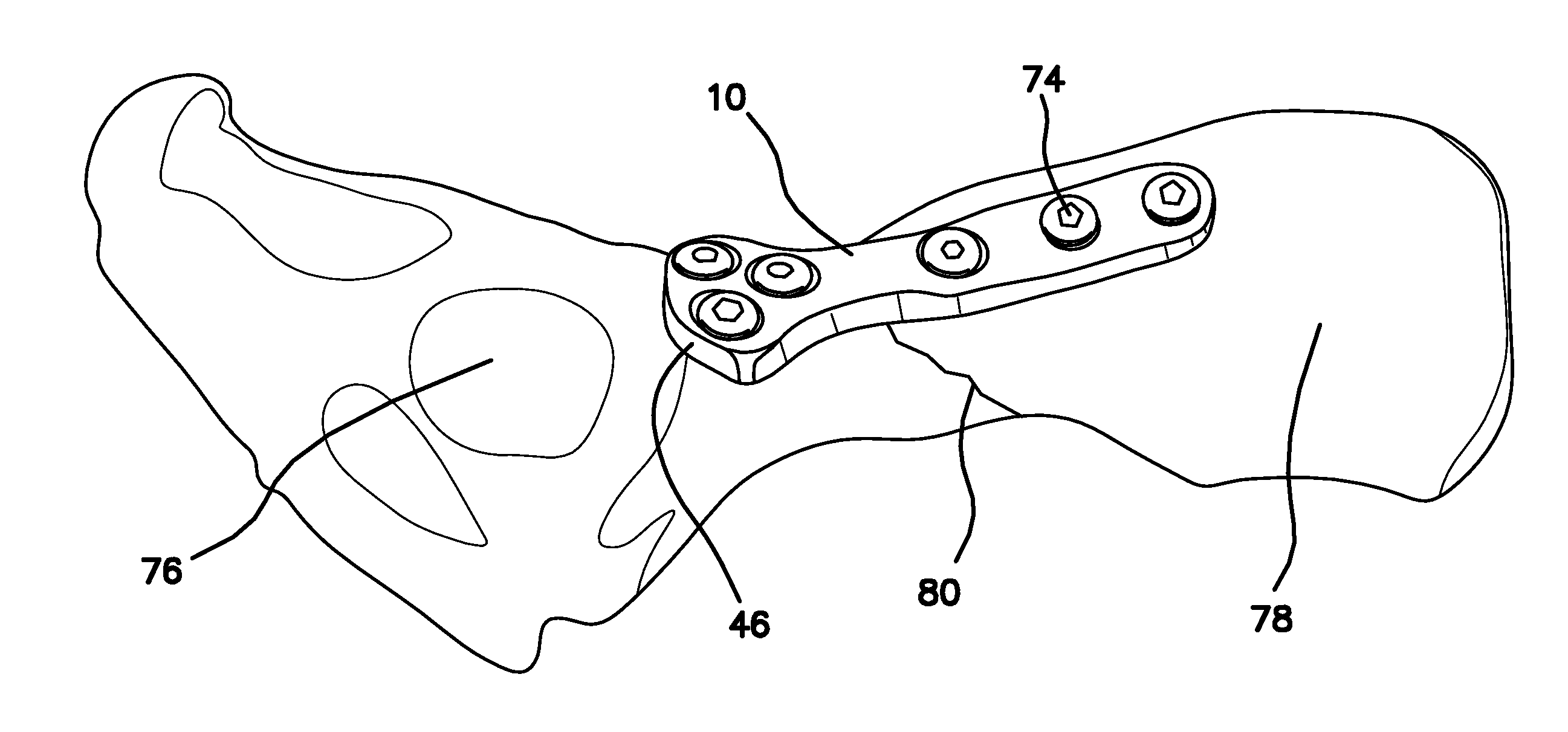
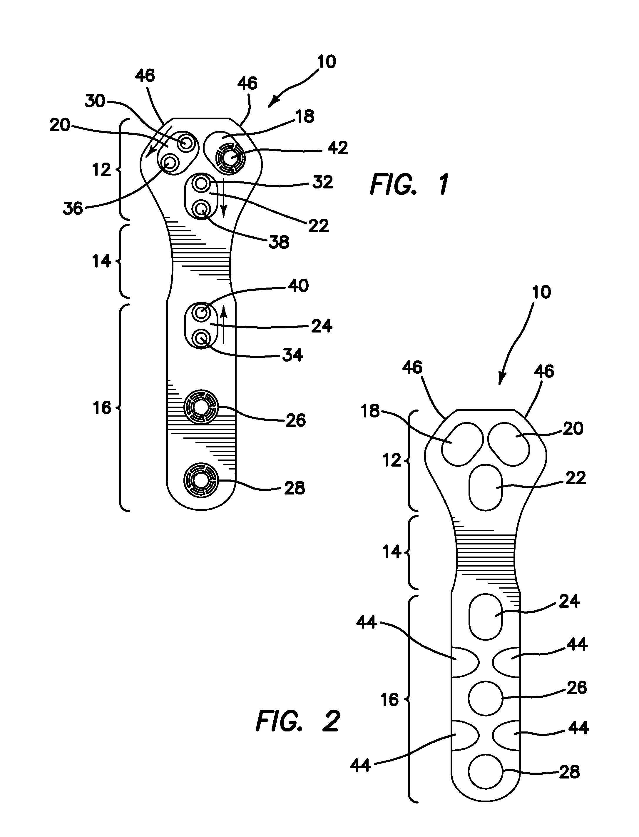
[0041]Referring now to the illustrated embodiment of the invention in more detail, in FIGS. 1 and 2 there is shown a universal plate, generally denoted by reference numeral 10. The plate 10 is comprised of three main parts or portions including a head 12, a neck 14, and a body 16. Defined within the plate 10 are six drive apertures, a right proximal aperture 18, a left proximal aperture 20, a center proximal aperture 22, a first body aperture 24, a second body aperture 26, and a third body aperture 28.

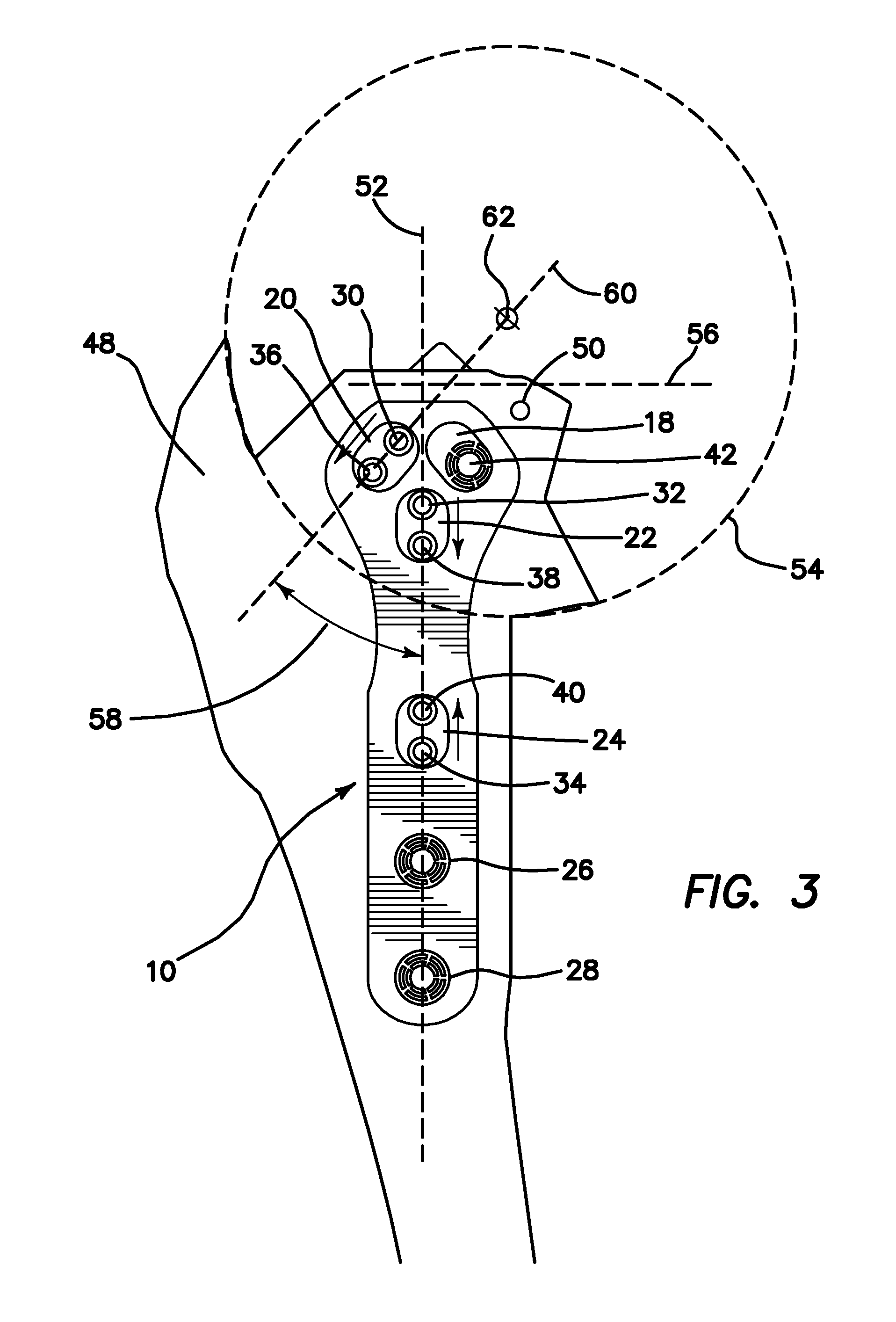
[0042]The right proximal aperture 18, left proximal aperture 20, center proximal aperture 22, and first body aperture 24 are substantially elongated or oval along an elongate axis, and the second body aperture 26 and third body aperture 28 are substantially circular in shape. In the head 12, both the right and left proximal apertures 18, 20 are defined within the plate 10 so that the elongate axis of each aperture 18, 20 is orientated 30 degrees from the longitudinal axis of the plate ...


PUM


Abstract

A universal surgical plate comprises a symmetrical design which enables it to be used for both right and left sided TPLO procedures as well as other orthopedic procedures on other bilaterally symmetric bones. The plate provides a 30 degree angle compression force with respect to the longitudinal axis of the plate in order to ensure maximum compression across an osteotomy or fracture. The plate is affixed across the osteotomy or fracture with orthopedic screws disposed through a plurality of elongated and circular drive apertures. The drive apertures are defined within the plate at sufficient distances to preserve the integrity of the underlying bone. The body of the plate also comprises a plurality of notches for improving periosteal circulation. The head of the plate includes a pair of recessed corners so that the plate may be implanted close to an assisting jig pin on smaller breeds of canines.

Description

RELATED APPLICATIONS [0001]The present application is related to U.S. Provisional Patent Application, Ser. No. 61 / 121,863, filed on Dec. 11, 2008, which is incorporated herein by reference and to which priority is claimed pursuant to 35 USC 119.BACKGROUND OF THE INVENTION [0002]1. Field of the Invention[0003]The invention relates to the field of orthopedic surgical implants for animals, specifically orthopedic surgical implants for use during tibial plateau leveling osteotomy (TPLO).[0004]2. Description of the Prior Art[0005]When the cranial cruciate ligament of an animal such as a canine ruptures, the stifle joint of the animal becomes unstable and causes a decrease in mobility and an increase in arthritis. To correct this condition, a procedure well known in the art called tibial plateau leveling osteotomy (TPLO) is performed which keeps the stifle joint stable as well as prevents the femur from sliding down on the slope of the tibial plateau during weight bearing.[0006]Several de...

Claims


Application Information

Patent Timeline
IPC IPC(8): A61B17/88A61B17/80
CPCA61B17/8085A61B17/8014A61B17/8061
Inventor BOROSTYANKOI, FRANKNORTON, JEFFREY
Owner VETERINARY IMPLANTS DIRECT
Why Eureka
Try Eureka