
Multi-Core Processing System for Vehicle Control Or An Internal Combustion Engine Controller

a multi-core processing system and controller technology, applied in the field of failure diagnosis of multi-core cpu (central processing unit) systems, can solve the problems of increasing the cost and mounting capacity, increasing the resource consumption of the cpu, and the viewpoint of cost performance and mountability, so as to achieve the effect of less computation burden

Active Publication Date: 2010-06-03
HITACHI ASTEMO LTD
View PDF16 Cites 20 Cited by
  • Summary
  • Abstract
  • Description
  • Claims
  • Application Information

AI Technical Summary

Benefits of technology

[0003]As described above, the system, in which the data is compared in consistency, is for a purpose of improving the reliability. That is, it is assumed that the system executes the same processes on the plurality of processors or cores to build up the redundant system by using its processed result. The failure diagnosis method proposed by the JP-A-3-196232 has a problem such that a resource consumption is increased for the CPU, since the normal computation process is executed respectively on the plurality of CPUs or cores to then compare these processed results. For a purpose of further improving the processing speed in the above-mentioned systems, it is necessary to increase the number of processors or cores, causing an increase of cost and mounting capacity. In the case of a vehicle control apparatus, it is difficult to apply the above-mentioned systems to it by causing a viewpoint of a cost performance and mountability. In relation to the above-mentioned problems, the JP-A-6-332874 has proposed the system in which the test program for use in the failure diagnosis is started to execute on the respective processors while executing a dispersed process. However, since this test program is used for a computation process different from a normally executed computation process, there is a problem as a computation burden for the respective processors or cores.
[0004]An object of the invention is to realize a failure determination for the plurality of cores on the vehicle control apparatus using a multi-core CPU system with compatibility between improvements of the reliability and processing speed, while restraining a redundant computation process caused by the special test program etc. and the resource consumption of CPU.
[0026]According to the invention, the process is executed simultaneously on the plurality of cores, so that the resource of cores can be used effectively. A special test program is unnecessary, so that the failure diagnosis can be realized for the multi-core system with a computation burden less.

Problems solved by technology

The failure diagnosis method proposed by the JP-A-3-196232 has a problem such that a resource consumption is increased for the CPU, since the normal computation process is executed respectively on the plurality of CPUs or cores to then compare these processed results.
For a purpose of further improving the processing speed in the above-mentioned systems, it is necessary to increase the number of processors or cores, causing an increase of cost and mounting capacity.
In the case of a vehicle control apparatus, it is difficult to apply the above-mentioned systems to it by causing a viewpoint of a cost performance and mountability.
However, since this test program is used for a computation process different from a normally executed computation process, there is a problem as a computation burden for the respective processors or cores.

Method used


Image

  • Multi-Core Processing System for Vehicle Control Or An Internal Combustion Engine Controller
  • Multi-Core Processing System for Vehicle Control Or An Internal Combustion Engine Controller
  • Multi-Core Processing System for Vehicle Control Or An Internal Combustion Engine Controller

Examples


first embodiment

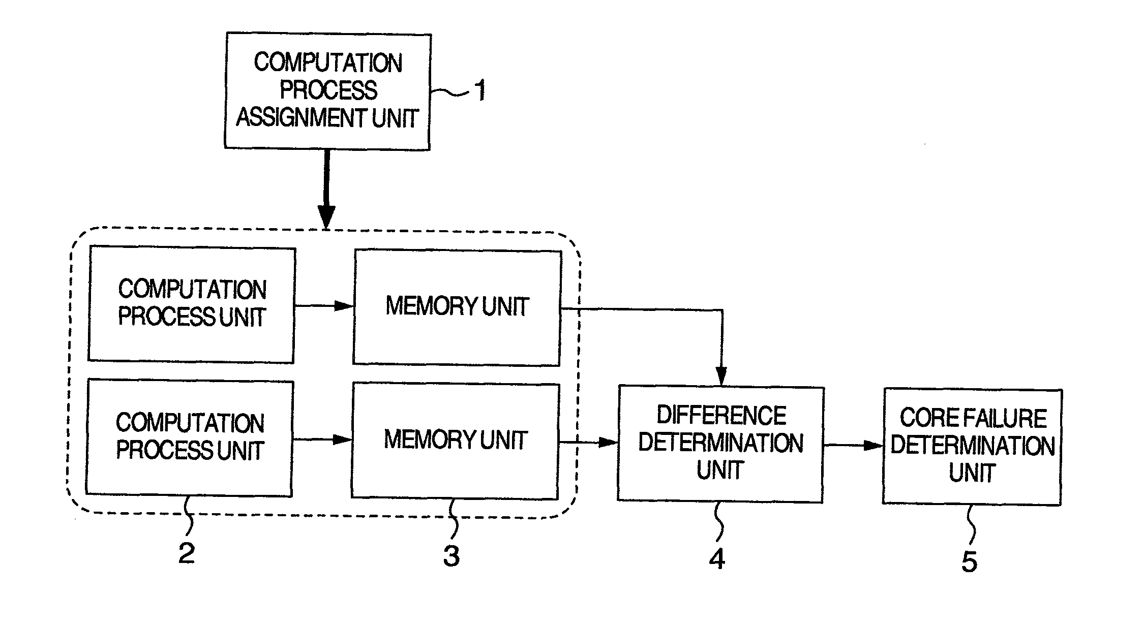
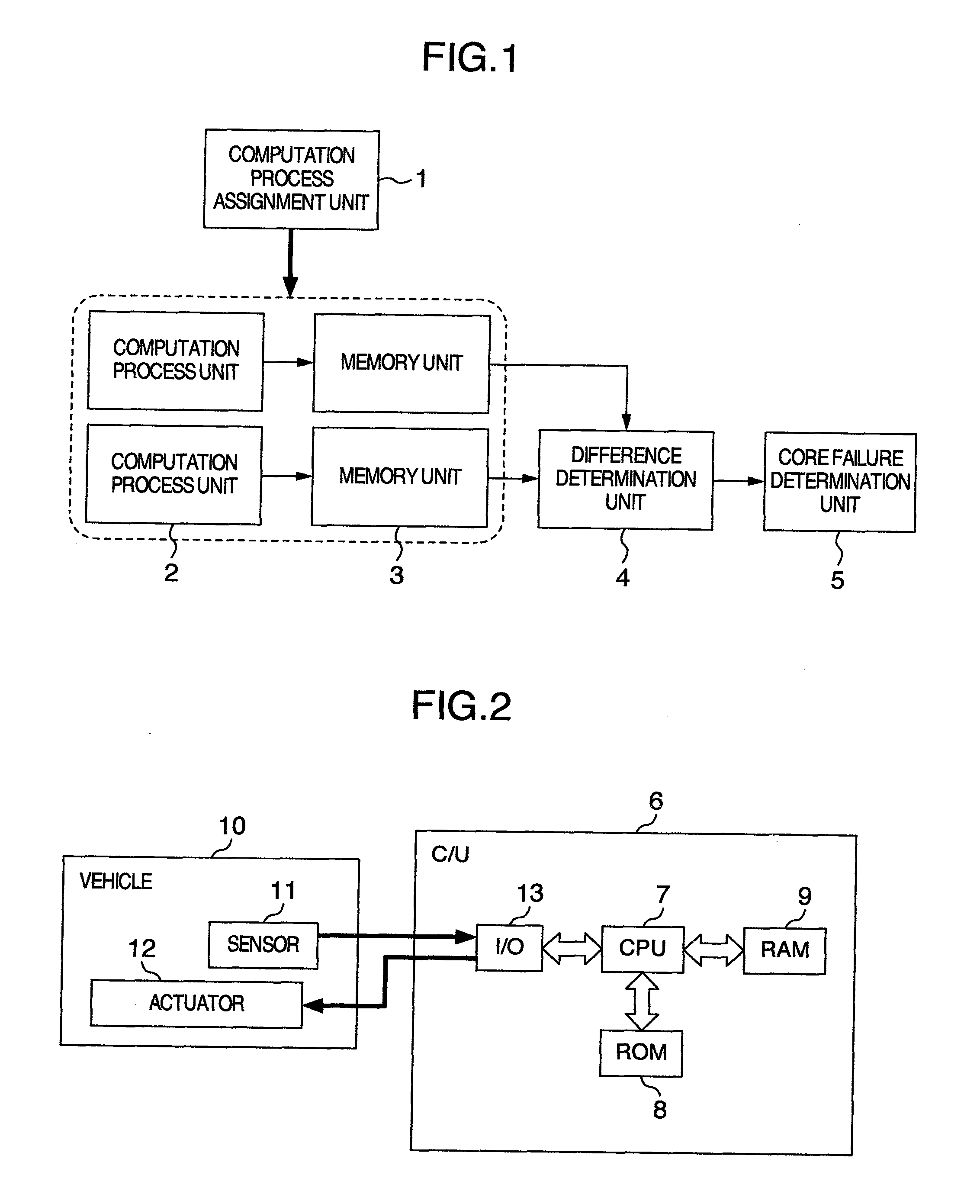
[0059]A first embodiment of the present invention will be described with reference to the drawings. FIG. 1 is a basic configuration diagram of the invention. As shown in FIG. 1, a vehicle control multi-core system includes a computation process unit 2 for controlling a device mounted on a vehicle, a memory unit 3 for storing a result obtained by the computation process unit 2, a computation process assignment unit 1 for allocating the computation process unit 2 to different core for each computation period, a difference determination unit 4 for determining whether a difference between the result obtained in the present period and the result in the previous period is present in a predetermined range, and a core failure determination unit 5 for determining that a failure occurs on the core executing the computation process in the present period when the a difference determination unit 4 determines that the difference is not present in the predetermined range. FIG. 2 is an entire confi...

second embodiment

[0077]A second embodiment of the invention will be described below. A different point of this embodiment from the first embodiment is the failure determination at the step S3. This operation will be described with reference to a flowchart in FIG. 11.

[0078]An operation of steps S4 and S5 is the same as that shown in FIG. 6. The process following the step S5 proceeds to a step S10. At the step S10, a difference between a moving average value stored in advance and the present value is calculated. The moving average value will be described later at a step S11. An operation of steps S7 to S9 is the same as that shown in FIG. 6. When the core is determined as the normal at the step S8, the process proceeds to the step S11. At the step S11, the present value is added to the moving average value stored in advance to calculate a new moving average value. A calculation method of the moving average value may be a method of a simple moving average or a weighted moving average. The determination...

third embodiment

[0081]A third embodiment will be described below, which corresponds to claim 3 in the invention. A different point of this embodiment from the second embodiment is the failure determination at the step S3. This operation will be described with reference to a flowchart in FIG. 14.

[0082]An operation of steps S4 and S5 is the same as that in FIG. 6. The process following the step S5 proceeds to a step S12. At the step S12, the predetermined range for use in the step S7 is calculated from the moving average value stored in advance. A calculation method of the predetermined rage corresponds to the following expressions (2), (3).

ΔTimin=−α×|moving average value|  (2)

ΔTimax=+α×|moving average value|  (3)

[0083]where α is an arbitrary coefficient equal to or greater than 1. This value makes large to be able to reduce an error determination for the failure determination, in contrast, it has a property of such that a detection accuracy becomes low for the failure. The calculation method of usin...


PUM


Abstract

A vehicle control multi-core system for controlling a device mounted on a vehicle by using a plurality of cores, includes a computation process unit that is executed on the plurality of cores and required for the control of the device, and a core failure determination unit that compares a result of a computation process executed by the computation process unit at a specific timing on a specific core among the plurality of cores, with a result of a computation process executed by the computation process unit at a timing different from the specific timing on another core different from the specific core among the plurality of cores to determine that a failure occurs on the specific core.

Description

BACKGROUND OF THE INVENTION[0001]The present invention relates to a built-in control device for controlling the device on a vehicle, and in particularly to a failure diagnosis for a multi-core CPU (Central Processing Unit) system configured by a plurality of CPUs.[0002]For a purpose of improving a reliability and a processing speed of the control device, there have increased cases of configuring the CPU in a control computer by a plurality of processors and of using the multi-core CPU configured by a plurality of CPUs. In the above-mentioned computer, when a processor or core is failed, it is necessary to detect immediately its failure, halt the processor or core, and apply a process to it to prevent an adverse affect on the control. For example, a redundant system has been well known as disclosed in JP-A-3-15946. The JP-A-3-15946 discloses a system in which data output from a plurality of redundancy subsystems is compared with each other to then select an output, the data of which ...

Claims


Application Information

Patent Timeline
IPC IPC(8): G06F11/07
CPCG06F11/1637G06F11/165G06F11/188G06F11/181G06F11/1695
Inventor OHKAWA, KEIICHIRO
Owner HITACHI ASTEMO LTD
Learn More