High performance airfoil with co-flow jet flow control

a flow control and high-performance technology, applied in the direction of airflow influencers, drag reduction, wings, etc., can solve the problems of increasing the difficulty of controlling system implementation, increasing the weight of the aircraft, and increasing the power loss of the propulsion system

Inactive Publication Date: 2010-05-27
UNIV OF MIAMI
View PDF6 Cites 30 Cited by
  • Summary
  • Abstract
  • Description
  • Claims
  • Application Information

AI Technical Summary

Benefits of technology

[0007]The aerodynamic structure of the present invention improves upon known structures, systems and techniques for flow control with respect to an airfoil. In an exemplary embodiment, the aerodynamic structure includes an airfoil having an injection slot on the suction surface of the airfoil near the leading edge, as well as a recovery slot on the suction surface of the airfoil near t...

Problems solved by technology

However, the penalty to the propulsion system (power loss) is often significant for some of the prior art flow control methods.
However, these methods require complicated actuation and sensor systems which may increase t...

Method used


Image

  • High performance airfoil with co-flow jet flow control
  • High performance airfoil with co-flow jet flow control
  • High performance airfoil with co-flow jet flow control

Examples


Embodiment Construction

[0015]Prior to setting forth an exemplary embodiment of the present invention, the general characteristics and features of an airfoil will be identified and defined as referred to herein.

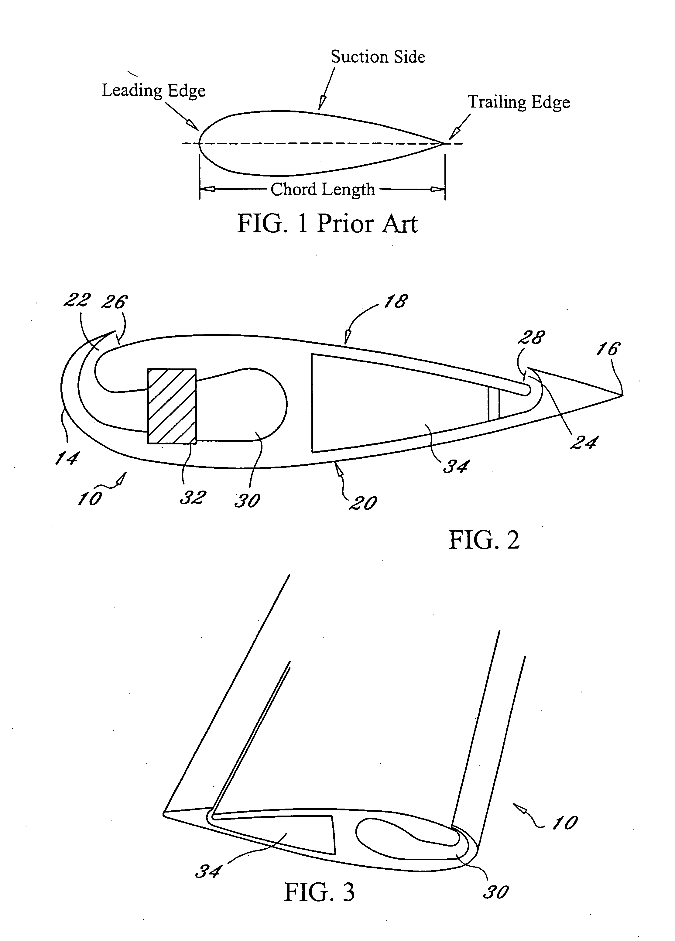
[0016]Now referring to FIG. 1, an airfoil generally includes a leading edge, a trailing edge, an “upper surface,” a “lower surface,” and a chord. The leading edge is that which encounters a fluid flow first, i.e., the “front” of the airfoil. The trailing edge is at the rear point of the airfoil, where the fluid flow over the upper surface meets the fluid flow across the lower surface of the airfoil.

[0017]Both the “upper” and “lower” surfaces are usually curved, with the “upper” surface having a larger curvature, and thus a larger surface length spanning from the leading edge to the trailing edge of the airfoil. Because the of the greater length across the “upper” surface, according to Bernoulli's theorem, the fluid flowing over the “upper” surface of the airfoil has a higher velocity than the fluid ...


PUM


Abstract

An aerodynamic system providing an airfoil having a chord length, a leading edge, and a trailing edge. The airfoil further includes a first airfoil surface extending from the leading edge to the trailing edge, a second airfoil surface opposite the first airfoil surface, extending from the leading edge to the trailing edge, an injection opening in the first airfoil surface, and a recovery opening in the first airfoil surface located between the injection opening and the trailing edge. A pressurized fluid source is in fluid communication with the injection opening and a vacuum source is in fluid communication with the recovery opening. An exemplary use of the aerodynamic system of the present invention provides the ejection of a mass of fluid out of the injection opening along a surface of the airfoil and drawing a mass of fluid into the recovery opening.

Description

CROSS-REFERENCE TO RELATED APPLICATION[0001]This application is related to and claims priority to U.S. Provisional Patent Application Ser. No. 60 / 603,212, filed Aug. 20, 2004, entitled HIGH PERFORMANCE AIRFOIL WITH CO-FLOW JET FLOW CONTROL, the entirety of which is incorporated herein by reference.STATEMENT REGARDING FEDERALLY SPONSORED RESEARCH OR DEVELOPMENT[0002]This invention was made by an agency of the United States government or under a contract with an agency of the United States Government. The name of the U.S. Government agency and the Government contract number are NASA-Contract No. NNL04AA39C.FIELD OF THE INVENTION[0003]The present invention relates to airfoils and flow control.BACKGROUND OF THE INVENTION[0004]Selected airframe, wing and control surface configurations; propulsion, control and guidance systems; and material properties combine to allow an aircraft to take flight and directly affect how the aircraft interacts with and moves through its atmospheric environme...

Claims


Application Information

Patent Timeline
IPC IPC(8): B64C21/04B64C21/06
CPCB64C21/025B64C2230/04B64C2230/06Y02T50/166Y02T50/10
Inventor ZHA, GECHENPAXTON, CRAIG
Owner UNIV OF MIAMI
Why Eureka
Try Eureka