
Display device, method of driving display device, and computer program

a display device and display device technology, applied in the direction of instruments, color signal processing circuits, computing, etc., can solve the problems of deterioration of luminescence elements, picture display with colour temperature different from the desired one,

Active Publication Date: 2010-05-13
JOLED INC
View PDF7 Cites 7 Cited by
  • Summary
  • Abstract
  • Description
  • Claims
  • Application Information

AI Technical Summary

Benefits of technology

[0011]The display device may further include a linear converter for converting a picture signal with a gamma characteristic into a picture signal with a linear characteristic. According to such a configuration, a linear converter converts a picture signal with a gamma characteristic into a picture signal with a linear characteristic. The picture signal with a linear characteristic converted by the linear converter is input to the luminescence amount detector, and a luminescence amount is detected from the picture signal. As a result, each of the various signal processes can be readily executed.
[0013]The coefficient calculator may calculate a coefficient for adjusting, to luminance of a colour at lowest luminance, luminance of other colours, as a result of acquiring the luminance information by the luminance acquirer. According to such a configuration, a coefficient calculator calculates a coefficient for adjusting, to luminance of a colour at lowest luminance, luminance of other colours, as a result of acquiring the luminance information by a luminance acquirer. As a result, a picture is displayed with luminance lowered by adjusting the luminance of the rest of the colours to the luminance of the colour at the lowest luminance so that the deterioration speed of a self-luminescence element can be slowed.
[0014]The luminescence amount detector may detect luminescence amounts for a plurality of regions on a screen, and a signal level calculator may adjust a luminescence amount adapting to an area with most lowered luminance. According to such a configuration, a luminescence amount detector detects luminescence amounts for a plurality of areas on a screen, and a signal level calculator adjusts a luminescence amount adapting to an area with most lowered luminance. As a result, the luminance of the whole screen is adapted to that of the area with the most lowered luminance, so that the colour temperature of the whole screen can be uniformed.
[0015]For the plurality of areas, the luminescence amount detector moves the areas up and down on a screen to detect a luminescence amount. According to such a configuration, in a case of detecting a luminescence amount, for the plurality of areas, the luminescence amount detector moves the areas up and down on a screen to detect a luminescence amount. As a result, the luminance on the screen can be detected thoroughly, and more advantageous adjustment on colour temperature can be executed.
[0020]According to the present invention as described above, it is possible to provide a display device, a method of driving the display device, and a computer program, which are novel and improved, and which are capable of calculating luminescence time from a picture signal and obtaining the luminance of a luminescence element based on the calculated luminescence time, and adjusting colour temperature based on the obtained luminance information.

Problems solved by technology

However, since the elements of a self-luminescence display device themselves emit light, the luminescence elements deteriorates if they continue emitting light.
Therefore, luminescence balance amongst three colours, red, green and blue, is disrupted as the luminescence elements deteriorate, and as a result, there has been an issue that a picture is displayed with colour temperature different from desired one.

Method used


Image

  • Display device, method of driving display device, and computer program
  • Display device, method of driving display device, and computer program
  • Display device, method of driving display device, and computer program

Examples


Embodiment Construction

[0091]Hereinafter, preferred embodiments of the present invention will be described in detail with reference to the appended drawings. Note that, in this specification and the drawings, elements that have substantially the same function and structure are denoted with the same reference numerals, and repeated explanation is omitted.

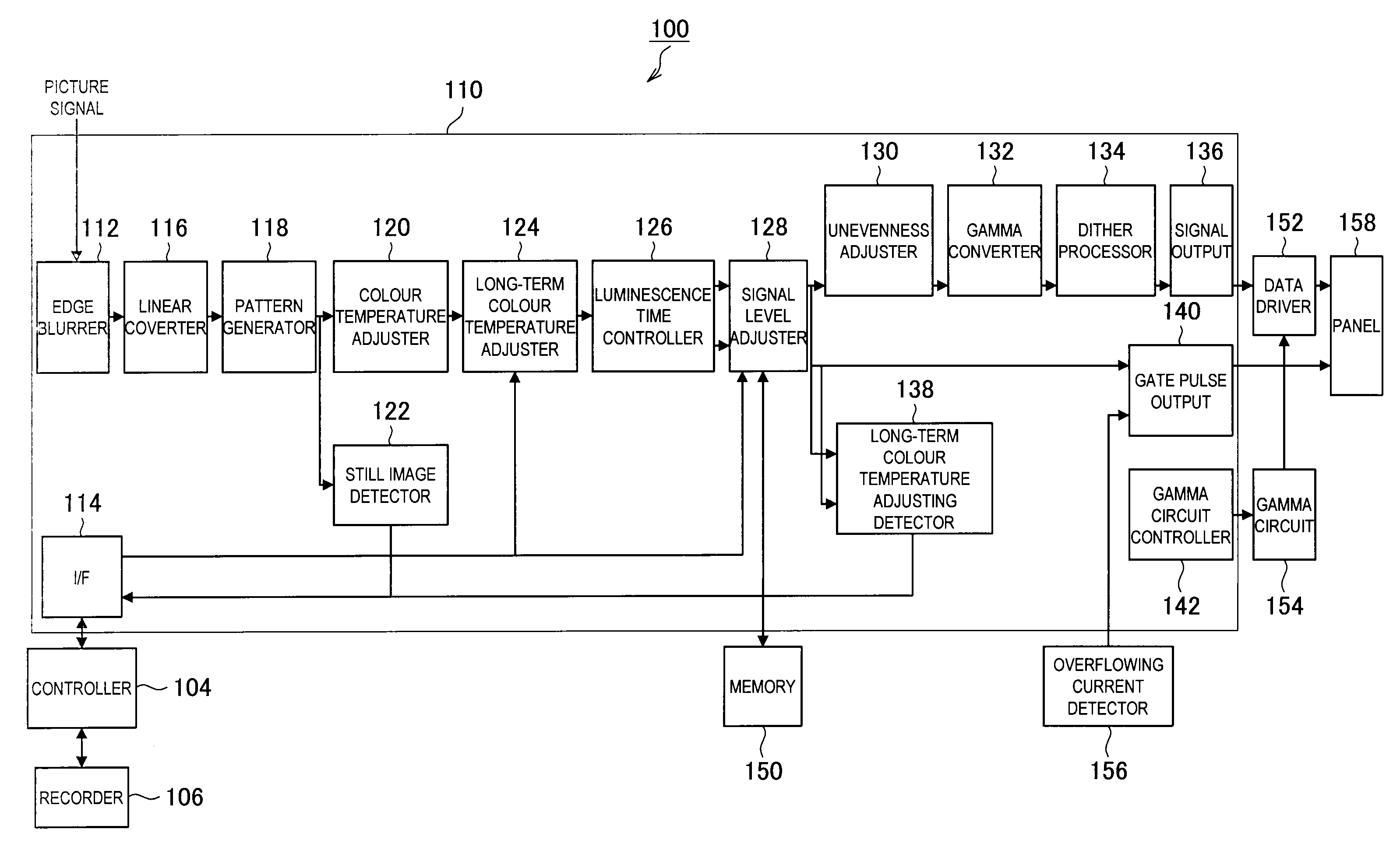
[0092]First, the configuration of a display device according to an embodiment of the present invention will be described. FIG. 1 is an illustration that illustrates a configuration of a display device 100 according to an embodiment of the present invention. In the following, the configuration of the display device 100 according to an embodiment of the present invention will be described with reference to FIG. 1.

[0093]As shown in FIG. 1, the display device 100 according to an embodiment of the present invention includes a controller 104, a recorder 106, a signal processing integrated circuit 110, a memory 150, a data driver 152, a gamma circuit 154, an over...


PUM


Abstract

There is provided a display device including a display unit having pixels, each of which includes a luminescence element for individually emitting light depending on a current amount and a pixel circuit for controlling a current applied to the luminescence element according to a picture signal, scan lines which supply a selection signal for selecting the pixels to emit light to the pixels in a predetermined scanning cycle, and data lines which supply the picture signal to the pixels, the pixels, the scan lines, and the data lines arranged in a matrix pattern, the display device including: a luminescence amount detector for inputting a picture signal with a linear characteristic to detect a luminescence amount from the picture signal; a luminescence time calculator for calculating a luminescence time for the luminescence element based on the luminescence amount detected by the luminescence amount detector; a luminescence time recorder for recording the calculated luminescence time; a luminance acquirer for acquiring luminance information of the luminescence element by use of the luminescence time recorded in the luminescence time recorder; a coefficient calculator for calculating a coefficient by which the picture signal is multiplied, based on the luminance information acquired by the luminance acquirer; and a coefficient multiplier for multiplying the picture signal by the coefficient calculated by the coefficient calculator.

Description

TECHNICAL FIELD[0001]The present invention relates to a display device and a method of controlling display device, and more particularly, to an active matrix type display device configured to have scan lines for selecting pixels in a predetermined scanning cycle, data lines for giving luminance information for driving the pixels, and pixel circuits for controlling a current amount based on the luminance information and allowing luminescence elements to emit light depending on the current amount, which are arranged in a matrix pattern, and to a method of driving the same.BACKGROUND ART[0002]For flat and thin display devices, liquid-crystal display devices using liquid crystal, and plasma display devices using plasma have been practically used.[0003]A liquid-crystal display device is a display device with backlight for displaying an image by changing the arrangement of liquid crystal molecules by applying voltage to transmit or intercept light from the backlight. And, a plasma display...

Claims


Application Information

Patent Timeline
Patent Type & Authority Applications(United States)
IPC IPC(8): G09G5/02G09G5/10G09G3/30
CPCG09G3/3225G09G2310/0232G09G2320/045G09G2320/048G09G2320/0666H04N9/73G09G2320/103G09G2340/0442G09G2340/16G09G2360/145G09G2360/16G09G2320/0673H10K59/351
Inventor MORI, HIDETOKIKUCHI, KENINOUE, YASUOMEGURO, TAKEYASHIDARA, HIDEHIKOITO, MASAHIROOSUMI, TOYO
Owner JOLED INC
Learn More