
Method and apparatus for monitoring waste removal and administration

a technology for monitoring and removing waste, applied in the field of methods and equipment for monitoring the movement of waste or refuse receptacles, can solve the problems of time and energy required by haulers, complicated coordination, and complicated tasks

Active Publication Date: 2010-05-13
ADVANCED CUSTOM ENGINEERED SYST & EQUIP
View PDF65 Cites 37 Cited by
  • Summary
  • Abstract
  • Description
  • Claims
  • Application Information

AI Technical Summary

Benefits of technology

[0019]This aspect of the invention may further one or more of the following steps: (1) providing instructions for affixing the means for transmitting on a subject of the permit; (2) providing a database on which identifying information for the permit holder is associated with the unique identifier; (3) providing a portable reader for receiving the wireless signal carrying the unique identifier from the means for transmitting; (4) transmitting a signal carrying the unique identifier from the portable reader to a central station at a separate location from the portable reader; (5) providing a computer at the central station; (6) inputting the unique identifier transmitted from the portable reader into the computer; (7) using a software on the computer to associate the unique identifier transmitted from the portable reader with the identifying information of the permit holder; and (8) transmitting at least some of the identifying information of the permit holder associated with the unique identifier transmitted from the portable reader from the central station to the portable reader.
[0020]Another aspect of the present invention is directed to a method for a municipality to control, track, and monitor waste or refuse receptacles. This method comprises the steps of: (1) requiring a permit for use of a waste receptacle; (2) issuing the permit associated with a discreet receptacle identifier; (3) providing a transmitter means attached to a discreet receptacle; and (4) transmitting a signal carrying data associated with the discreet receptacle identifier from the transmitter means. This aspect of the invention may further include the steps of: (1) providing a handheld receiver for receiving the signal from the transmitter means; (2) identifying a municipal code violation associated with a use of the waste receptacle; and / or (3) using the handheld receiver to automatically generate citations based on the municipal code violation.

Problems solved by technology

For large organizations this can be a very complicated task as there are many haulers and many customers needing their trash and recyclables collected, picked-up and hauled away.
This too requires time and energy for the haulers and / or representatives (of the service provider) to monitor and inspect.
For large organizations this can be a very complicated to coordinate and to verify that the charges for these services are fair and accurate as there are many service providers and many customers needing their compactors, bins and balers repaired.
However, it is not cost-effective of feasible for the dispatcher to be in constant contact with every vehicle out in the field.
Thus, it is impossible for the dispatcher to relay account information associated with each receptacle to a vehicle.
The dispatcher currently has no way of assuring that the special instructions are provided to the vehicle in a timely manner.
Some of this is caused by simply overloading receptacles.
Other times, a user may fall behind in payment of bills for removing refuse and waste, and the receptacles and surrounding areas will become over loaded with refuse.
It may also cause damage to the lane on which the receptacles are located.
Absent constant patrol of back lanes, municipalities often have no idea that these conditions exist until it is too late.
Even when patrolling the back lanes, it is difficult to impossible to determine which receptacles belong to which owners / addresses.
Finally, when a positive identification of the offending receptacle is able to be determined the process consumes so much time that the municipal employee is only able to investigate but a handful of the many violations that occur at any one time.

Method used


Image

  • Method and apparatus for monitoring waste removal and administration
  • Method and apparatus for monitoring waste removal and administration
  • Method and apparatus for monitoring waste removal and administration

Examples


examples

[0086]

PermitIdentificationPurposePermitInformationCarrierLocationTrash / RefuseThe Collection,AddressProtective PocketPlaced on insideRemovalStorage ofType ofwith adhesive onof lid for TrashTrash / RefuseContainerone sideContainer orfor RemovalPermit Numberoutside Largeand Size of& DateCompactor / BailerContainer,Term / PeriodCompactor orValidBailerRecyclablesCollection ofAddressProtective PocketPlaced on insideRemovalThe Collection,Type ofwith adhesive onof Lid forStorage andContainerone sideRecyclableRemoval ofPermit NumberContainer orRecyclable& Dateoutside LargeMaterials andTerm / PeriodCompactor / BailerSize ofValidContainer,Compactor orBailerGreaseThe CollectionAddressProtective PocketPlaced on insideBoxesand Storage ofType ofwith adhesive onof Lid forDiscardedContainerone sideRecyclableGrease forPermit NumberContainer orRemoval& Dateoutside of BoxTerm / PeriodValidBusinessTo ConductAddressProtective PocketPlaced on insideBusiness at aCity Namewith adhesive onof Window forCertain PremisePer...


PUM


Abstract

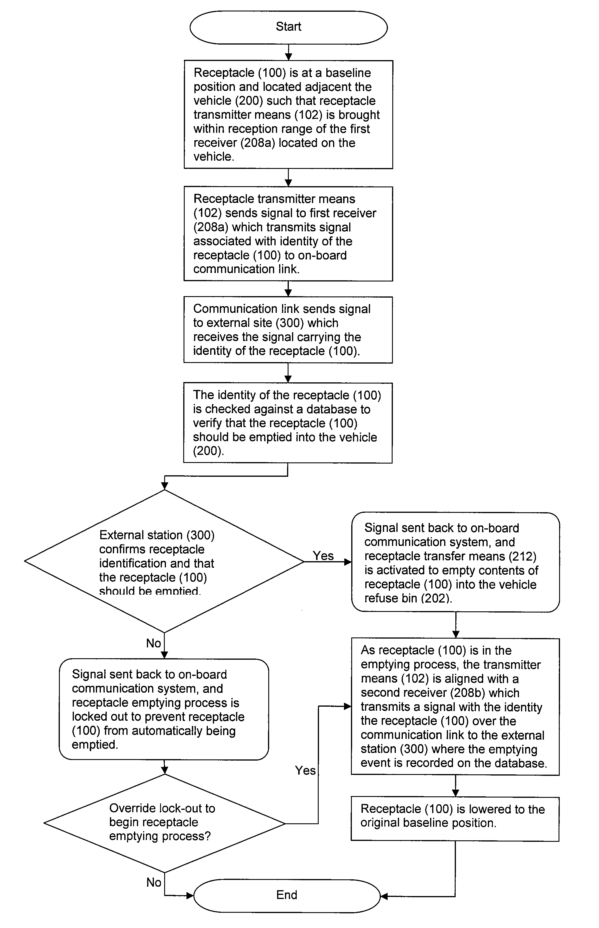
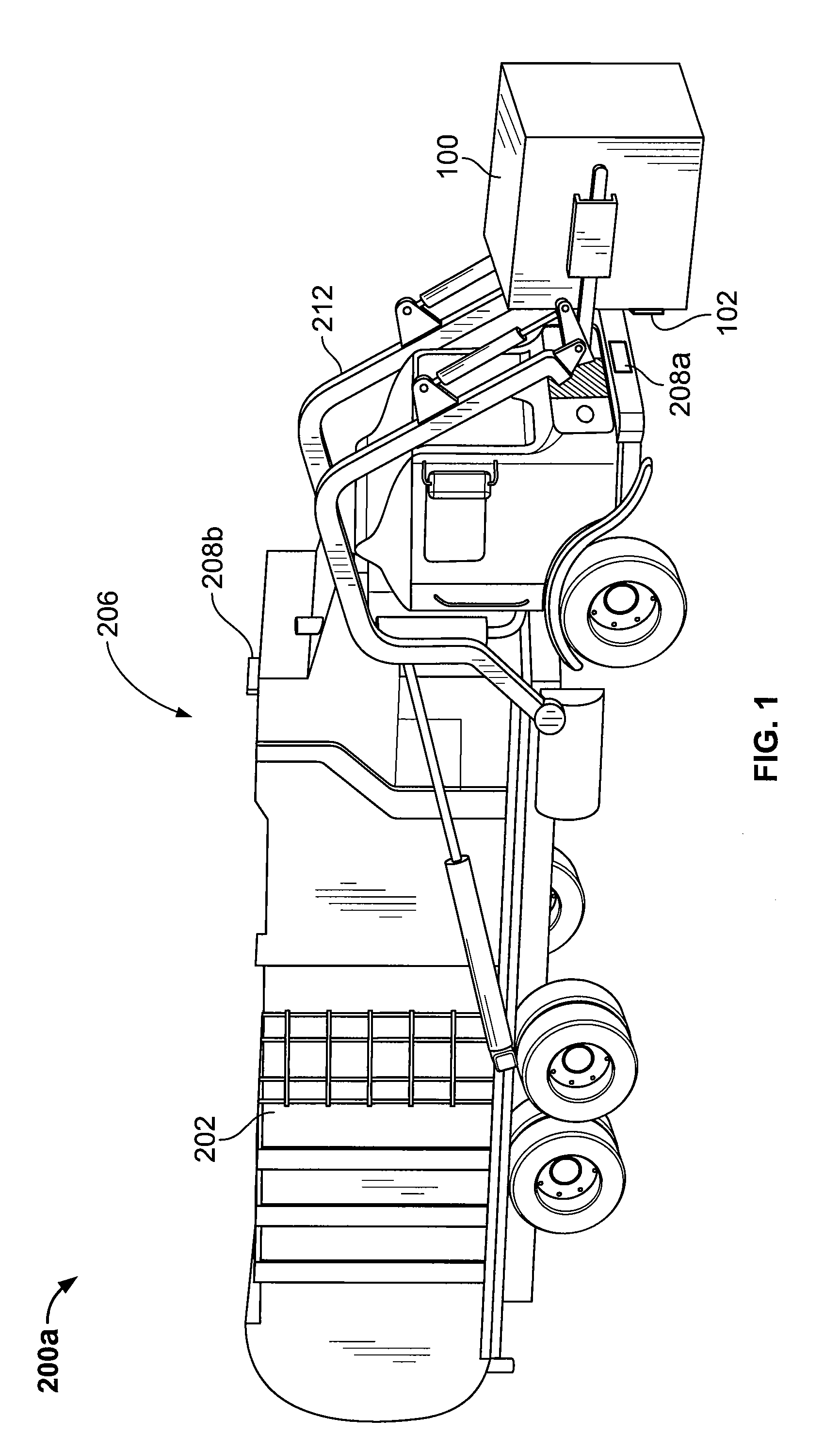
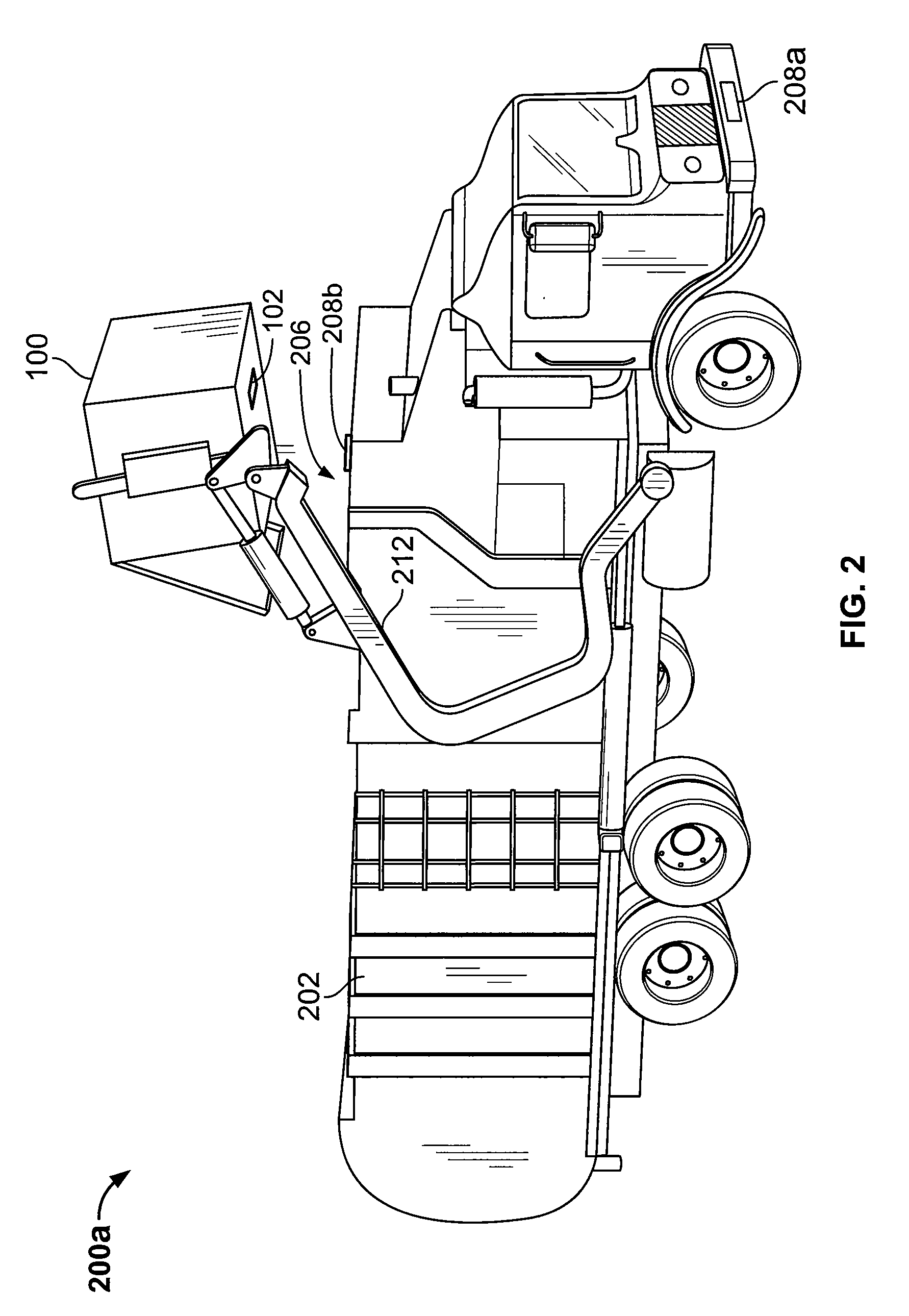
A method for a municipality to control, track, and monitor waste or refuse receptacles requires a permit for use of a waste receptacle. An issuing organization issues a permit associated with a discreet receptacle identifier. An RFID tag is provided with the permit and attached to a discreet receptacle. The RFID tag transmits a signal carrying data associated with the discreet receptacle identifier. The signal may be read by a portable reader carried by municipal personnel to record violations of municipal code associated with the use of the discreet receptacle.

Description

CROSS-REFERENCE TO RELATED APPLICATIONS[0001]This application is a continuation-in-part of application Ser. No. 12 / 267,367, filed on Nov. 7, 2008 and application Ser. No. 12 / 267,340, also filed on Nov. 7, 2008. Each application is hereby incorporated by reference as if fully set forth herein.FEDERALLY SPONSORED RESEARCH OR DEVELOPMENT[0002]N / ATECHNICAL FIELD[0003]The invention relates to refuse and waste removing and hauling. More particularly, the present invention relates to a method and apparatus for controlling, tracking, and monitoring movement of waste or refuse receptacles.BACKGROUND OF THE INVENTION[0004]The collection and transportation of trash and recyclables from residential, commercial, industrial and large residential facilities is a major industry in the United States and throughout the civilized world. Typically, trash and recyclables are accumulated and temporarily stored in waste material receptacles such as trash cans and dumpsters. When filled, or at regularly sc...

Claims


Application Information

Patent Timeline
Patent Type & Authority Applications(United States)
IPC IPC(8): G06K5/00
CPCB65F1/1484B65F2210/128B65F2210/164G06Q10/30G06K19/07758Y02W90/20B65F1/1473B65F3/041B65F2003/0279G06Q50/26Y02W90/00
Inventor FLOOD, CHRISTOPHER M.FISHER, MICHAEL S.
Owner ADVANCED CUSTOM ENGINEERED SYST & EQUIP
Learn More