
T-channel fixture-mounting pole clamp

a technology for mounting poles and fixtures, which is applied in the field of mounting brackets, can solve the problems of not allowing the head of the mounting bolt to be pulled out of the t-channel through the outward-facing surface, and achieve the effect of quick and easy fixture mounting and disassembly

Inactive Publication Date: 2010-04-29
JENESTREET FRANCIS CELEVATORON
View PDF20 Cites 24 Cited by
  • Summary
  • Abstract
  • Description
  • Claims
  • Application Information

AI Technical Summary

Benefits of technology

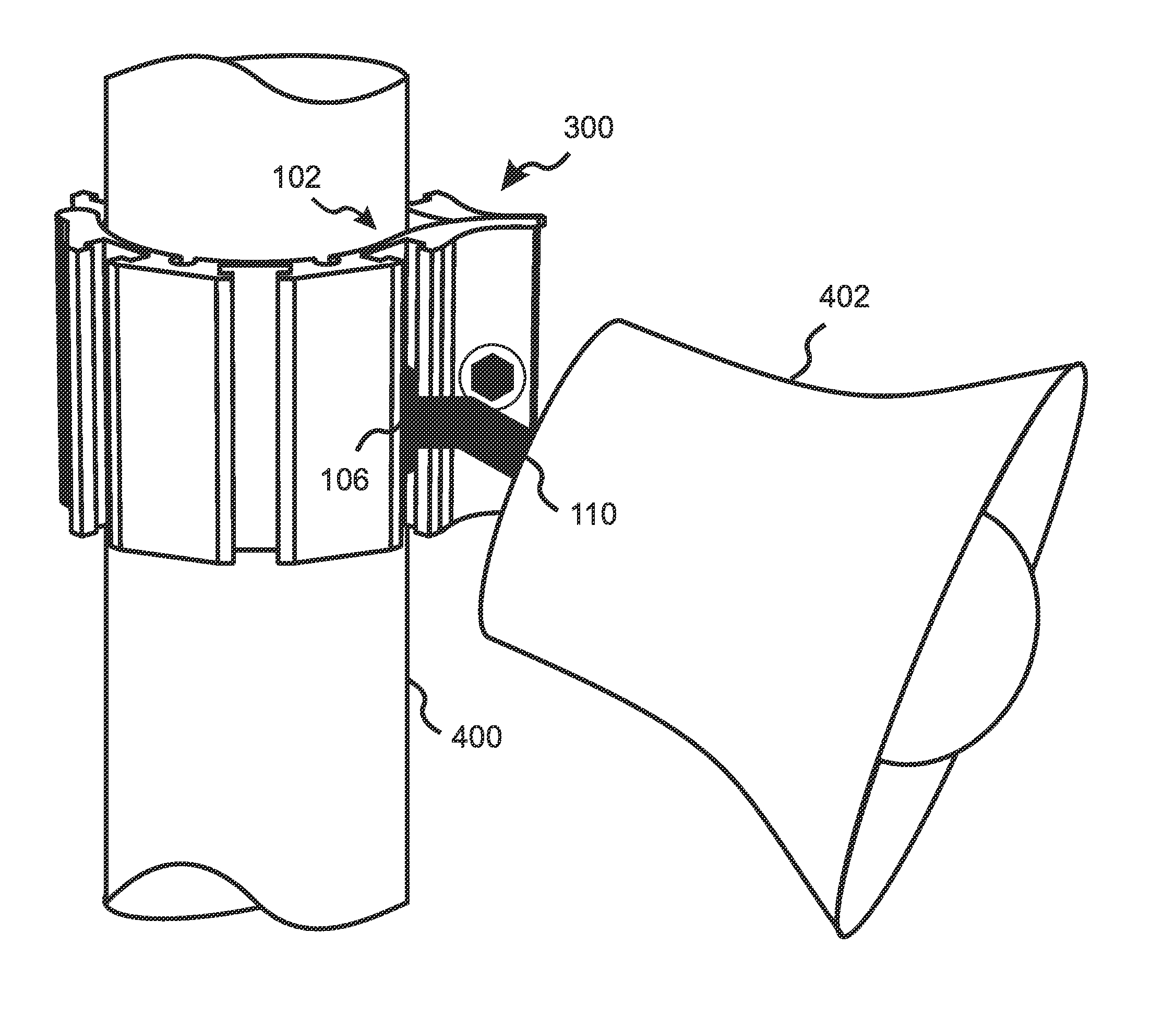
[0007]The present invention is a tent pole clamp that can be firmly attached to a center or side pole of a tent and can rigidly support a heavy fixture, while providing for quick and easy fixture mounting and dismounting. The invention is applicable in particular to tents that use rigid, load-bearing poles, such as tents that are commonly used in the special events industry. In various embodiments, the holding capacity of the clamp is up to 250 pounds.
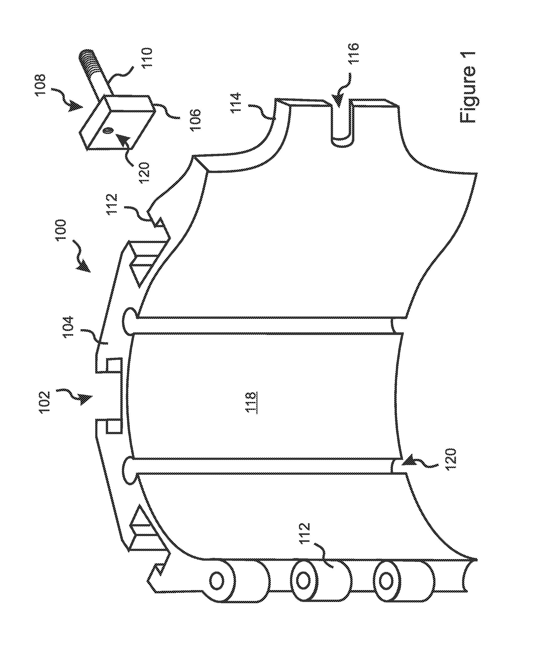
[0013]Various embodiments include a plurality of T-channels formed in one or more rigid rigid segments. Providing a plurality of T-channels enables attachment of a plurality of fixtures to the same clamp, and in some of these embodiments, the plurality of T-channels provides a plurality of mounting orientations, thereby providing options as to the direction in which an attached mounting bolt will be oriented.
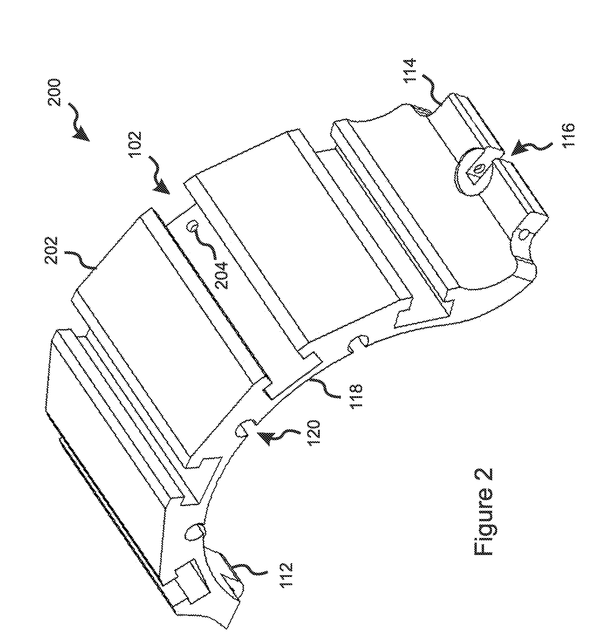
[0015]In various embodiments, the clamp of the present invention is formed by a pair of shaped rigid segments that are hinged to each other at hinged ends, the clamp being extendable around a pole and attachable thereto by pressing the unhinged ends of the rigid segments toward each other and trapping the pole therebetween. The unhinged ends can include flanges, and can be pressed together using a bolt, a cam lever, or any suitable means known in the art. The shaped rigid segments can be formed to accommodate a pole of any cross sectional size and shape, such as round, square, rectangular, or any arbitrary shape. In some of these embodiments, the rigid segments are substantially or completely identical in shape, thereby reducing manufacturing costs. Some of these embodiments include flexing T-channels running parallel to an inward-facing surface of each of the rigid segments. The flexing T-channels provide increased flexibility of the rigid segments in a direction that allows them to better conform to the shape of a pole as they are pressed against the pole. In some embodiments, the flexing T-channels are alternated in location with the T-channels along the rigid segment.

Problems solved by technology

It will be understood by one of average skill in the art that many other cross-sectional shapes are possible which will allow a mounting bolt to extend beyond the T-channel, but will not allow the head of the mounting bolt to be pulled out of the T-channel through the outward-facing surface.

Method used


Image

  • T-channel fixture-mounting pole clamp
  • T-channel fixture-mounting pole clamp
  • T-channel fixture-mounting pole clamp

Examples


Embodiment Construction

[0023]With reference to FIG. 1, the present invention is a clamp that can be firmly attached to a center or side pole of a tent and can rigidly support heavy fixtures, while providing for quick and easy fixture mounting and dismounting. The invention is applicable in particular to tents that use rigid, load-bearing poles, such as tents that are commonly used in the special events industry. In various embodiments the holding capacity of the clamp can be as high as 250 pounds.

[0024]The clamp of the present invention includes at least one rigid segment 100 having an outward-facing surface and at least one side surface 114 adjoining a boundary of the outward-facing surface (202 in FIG. 2, discussed in more detail below). A T-channel 102 is formed within the rigid segment 100 and runs parallel to the outward-facing surface 202. The T-channel 102 extends to and penetrates the outward-facing surface 202 and the side surface 114, so that a portion 106 of a compatible mounting structure 108 ...


PUM


Abstract

A pole clamp is disclosed that can firmly attach heavy fixtures to a pole, such as a center or side pole of a special-events tent, with quick and easy fixture mounting and dismounting. The head of a fixture-mounting bolt is downwardly slidable into a T-channel of the clamp, where it rests against a stop pin and rigidly supports the fixture until it is lifted out of the T-channel. A plurality of T-channels can provide for a plurality of fixture attachments at a plurality of orientations. In some embodiments, the clamp includes a pair of identical, hingedly joined, rigid aluminum segments that can be placed on opposite sides of the pole and compressed against the pole by pressing of the unhinged, flanged ends toward each other using a bolt, cam lever, or similar means. The rigid segments can be shaped to accommodate a pole of any cross-sectional size and shape.

Description

RELATED APPLICATIONS[0001]This application claims the benefit of U.S. Provisional Application No. 61 / 108,202, filed Oct. 24, 2008, incorporated herein by reference in its entirety for all purposes.FIELD OF THE INVENTION[0002]The invention relates to mounting brackets, and more particularly to brackets for attaching fixtures to a pole.BACKGROUND OF THE INVENTION[0003]Tents are frequently employed as temporary, low cost structures for a wide variety of activities, including camping trips, dining events, wedding receptions, concerts, expositions, and even circuses. A tent generally costs much less than a permanent structure, and is relatively quick to erect and to dismantle, easy to move, and has a minimal impact on the site where it is erected. A tent can also provide a feeling of being “outdoors,” while at the same time providing excellent shelter from the elements.[0004]One difficulty with using a tent to house an activity or event, especially when the activity is a party, celebrati...

Claims


Application Information

Patent Timeline
IPC IPC(8): F16M13/00
CPCF16B12/42F21V21/088F21V21/116Y10T24/1457G09F7/18G09F2007/1817F21V25/02
Inventor JENESTREET, FRANCIS CLIFTON
Owner JENESTREET FRANCIS CELEVATORON
Learn More