
Complex generator using solar and wind and wave

a generator and solar energy technology, applied in the direction of renewable energy generation, electric generator control, wind motor with solar radiation, etc., can solve the problems of inability to generate power by using wind energy and wave energy, solar energy cannot be generated cloud-side, and the actual application of commercial solar energy is not commercial, so as to save the total cost, easy installation, and strong rotation of the blower

Inactive Publication Date: 2010-04-22
KIM YUN - SE
View PDF0 Cites 38 Cited by
  • Summary
  • Abstract
  • Description
  • Claims
  • Application Information

AI Technical Summary

Benefits of technology

[0010]In a conventional art, one power plant is separately installed in a place such as a sea beach, a mountain, a river or something for obtaining an alternative energy by using a solar energy, a wind energy and a wave energy, which leads to a lot of cost and installation area. But, in the present invention, there is provided a combined power generation apparatus by using a basic facility needed for each power generation method for thereby saving the total cost. It is possible to strongly rotate a blower by using a twister generating twist wind. The shapes of wings are improved, so an upward wind flow can be used. When there is a typhoon, it is possible to protect a twister and wind force wings. The present invention can be easily installed in a place with less wind and low wind speed. Since a wave energy generation is possible in a sea beach, the use of an alternative natural energy is very efficient.

Problems solved by technology

Many studies disclose various technologies, but their actual applications are not commercial.
Since there is not disclosed any combined power generation method for using solar, wind and wave energies, a solar energy cannot be generated when it is cloud.
In addition, it is impossible to generate powers by using wind energy and wave energy when there are not wind or waves.
Since the power facilities installed separately from each other are influenced by means of a weather condition, an inter-operation is needed, but impossible due to the above reasons.

Method used


Image

  • Complex generator using solar and wind and wave
  • Complex generator using solar and wind and wave
  • Complex generator using solar and wind and wave

Examples


Embodiment Construction

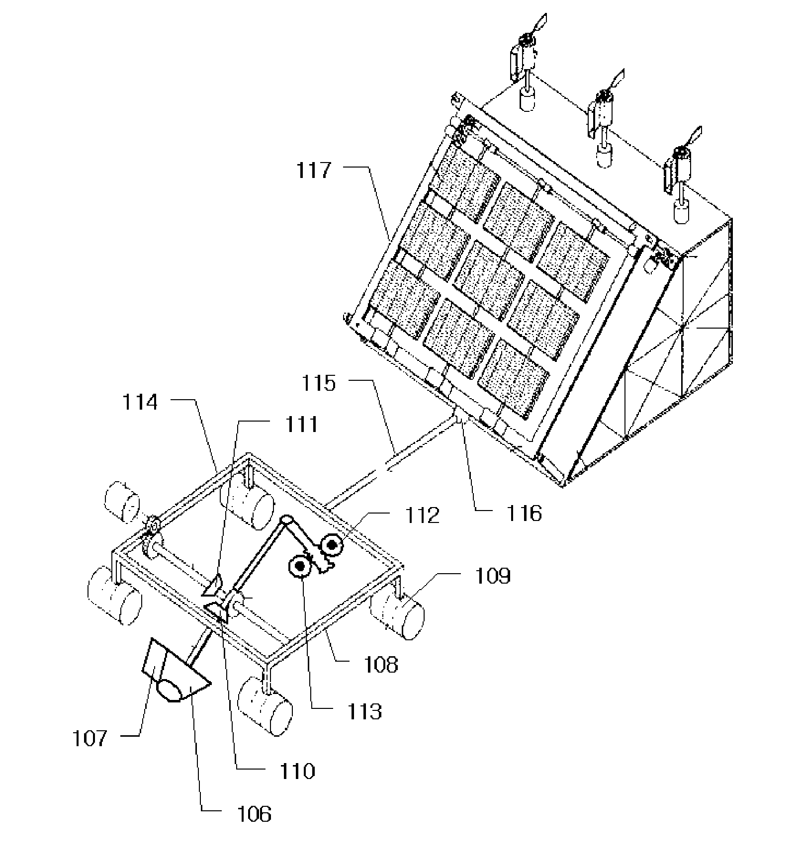
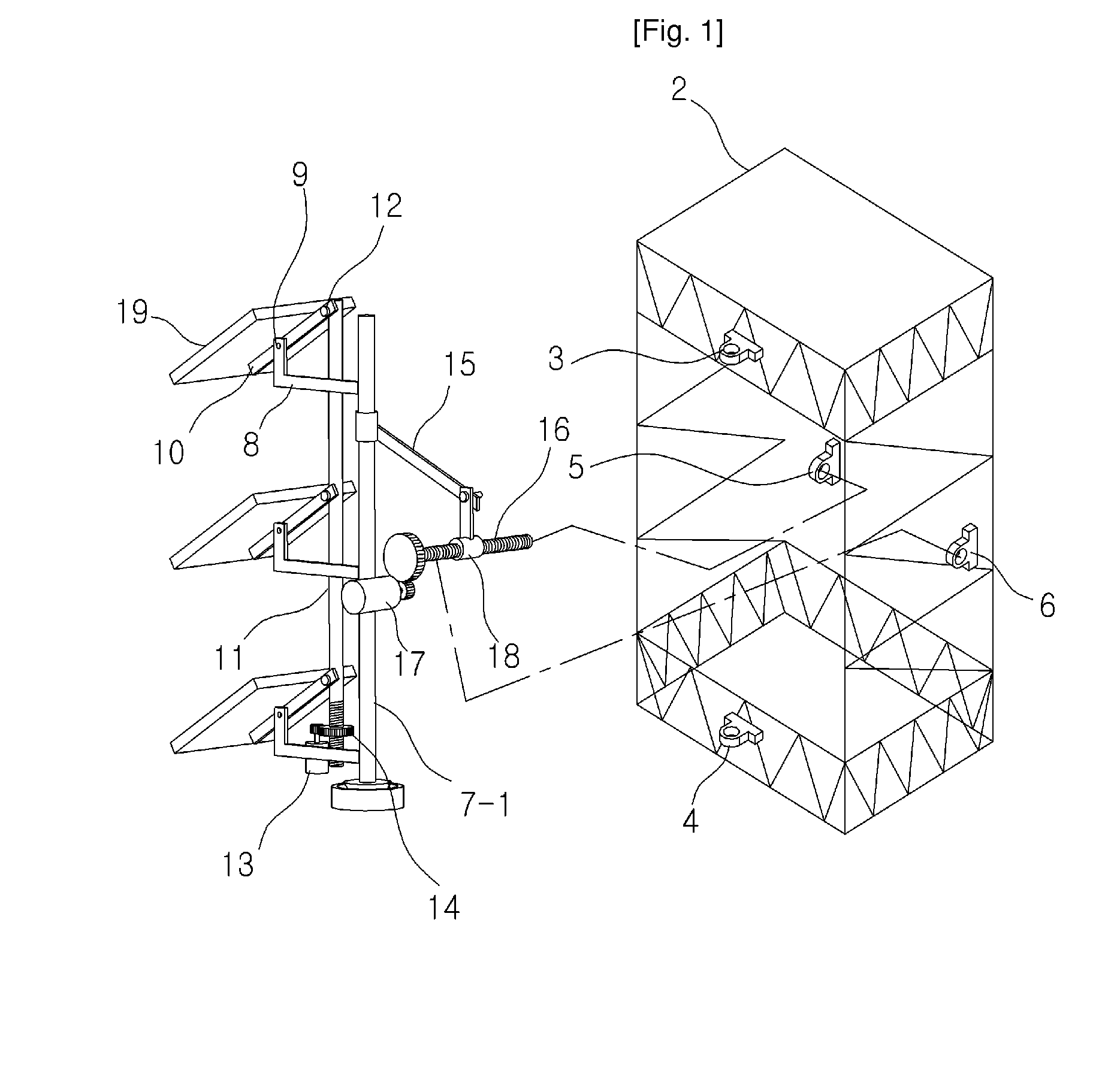
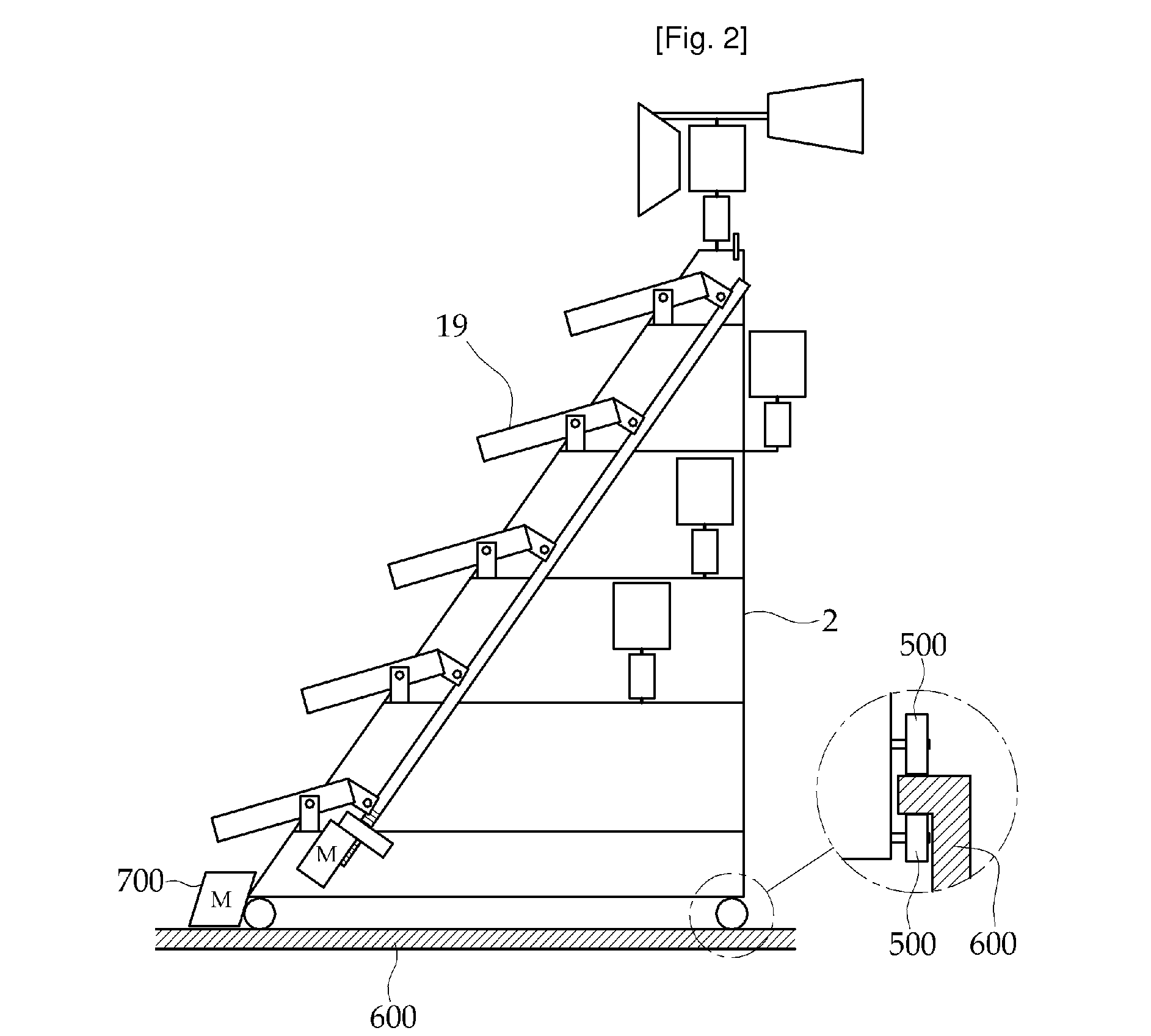
[0020]The facilities needed for a basic facility, which is constructed to more efficiently utilize the nature, such as a solar energy facility, a wind energy facility and a wave energy facility are combined, which leads to saving a lot of cost. The light collection plate is installed in South in multiple layers and rows, and the light collection plate can move toward the sun by using a sun tracing sensor in left and right directions, so that it is possible to collect the solar energy in maximum.

[0021]In the solar energy power generation facility structure, the side facing coming wind is gradually narrowed and bent, so a twisting wind is generated from an incoming wind. The wind force generated by the wings allows the blower installed in the center to rotate, so the generator is rotated. Rib grooves are formed in each wing with one end of each groove being twisted for enhancing wind efficiency, so it is possible to generate a desired energy by using an upwardly moving airflow.

[0022]I...


PUM


Abstract

A combined power generator using solar, wind and wave energies is disclosed. The combined power generator comprises a steel tower structure (2) having a solar energy power generation unit in which a plurality of light collection plates (19) are arranged in multiple rows and columns, a wind energy power generation apparatus which is installed on the top of the steel tower structure (2) and rotates by means of the wind, and a wave energy generation apparatus which is driven by means of the flow of water, wherein the steel tower structure, the wind energy power generation apparatus, and the wave energy generation apparatus are combined.

Description

TECHNICAL FIELD[0001]The present invention relates to a combined power generator using solar, wind and wave energies, and in particular to a combined power generator using solar, wind and wave energies in which a solar energy generator for generating power using a light collection plate, a wind energy generator for generating power using a pressure generated when wind blows, and a wave energy generator for generating power using waves in sea or river are combined, respectively.BACKGROUND ART[0002]An alternative energy has been studied for using energy instead of oil since a natural resource buried under the ground will be surely ended. Many studies disclose various technologies, but their actual applications are not commercial.[0003]It has been recognized that using an unlimited natural energy such as solar, wind and water energies is most ideal, so there are many researches on the same. In one example, there are a solar energy development technology in which the energy from sun lig...

Claims


Application Information

Patent Timeline
IPC IPC(8): E04H12/34H01L31/02F03B13/20F03D9/00
CPCF03D3/065F03D9/007Y02E10/74Y02E10/38Y02E10/465F03D9/008Y02E10/47F24S25/10Y02E10/46Y02E10/30F03D3/062F03G6/06F03D15/10F03D9/25F03D3/04
Inventor KIM, YUN SE
Owner KIM YUN - SE
Learn More