
Occipital plate for cervical fixation

Active Publication Date: 2010-04-15
K2M
View PDF19 Cites 42 Cited by
  • Summary
  • Abstract
  • Description
  • Claims
  • Application Information

AI Technical Summary

Problems solved by technology

Utilizing the maximum screw length possible is critical, because shorter screws do have reduced resistance to pullout.

Method used


Image

  • Occipital plate for cervical fixation
  • Occipital plate for cervical fixation
  • Occipital plate for cervical fixation

Examples


Embodiment Construction

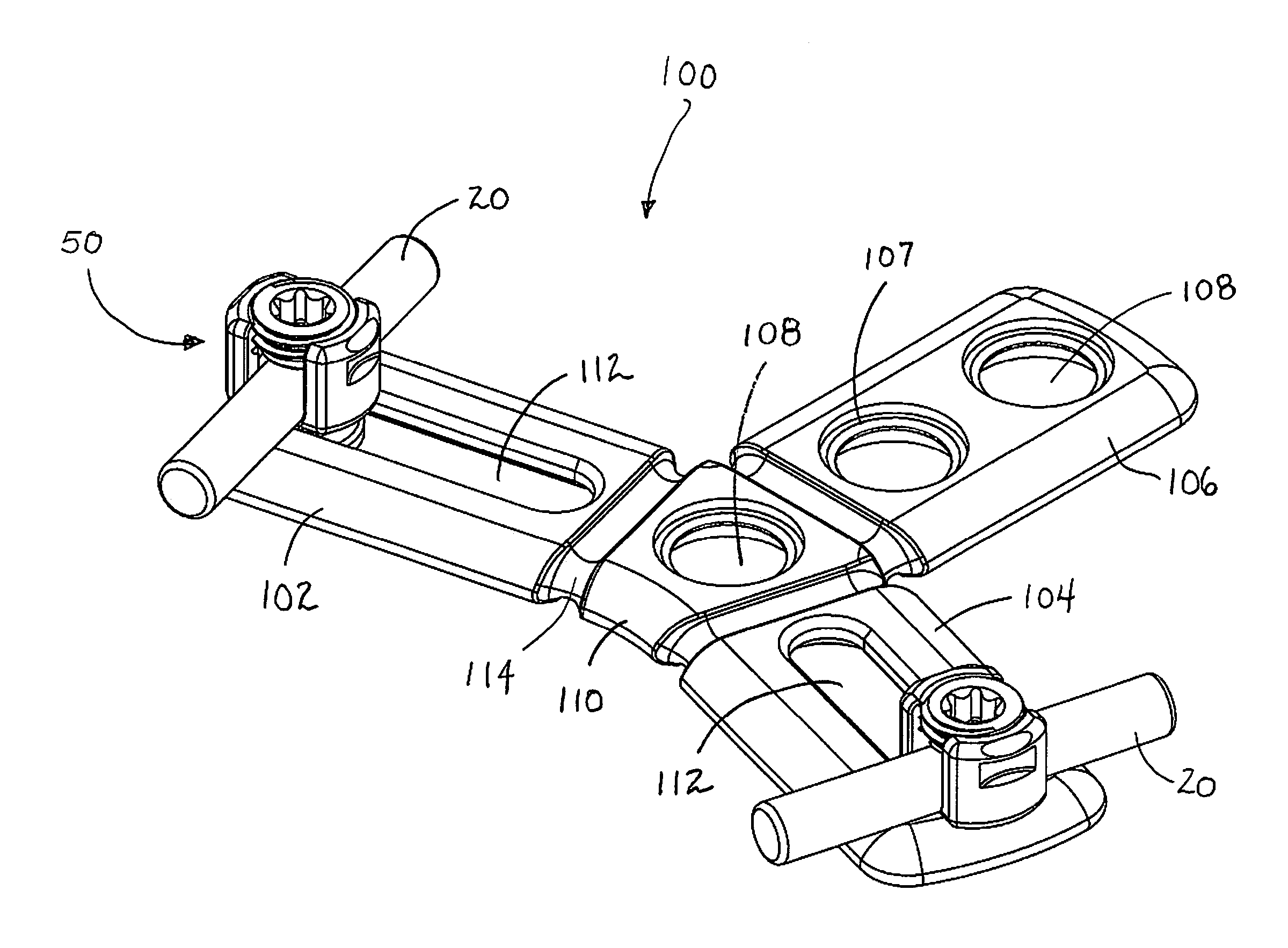
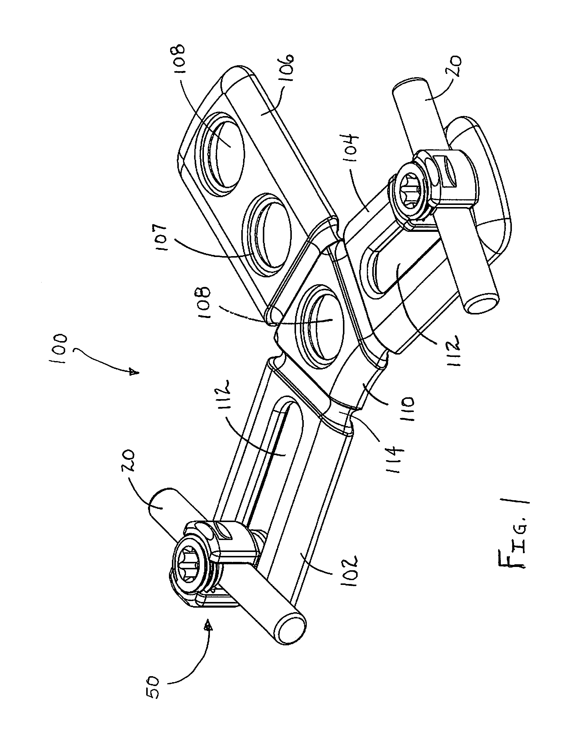
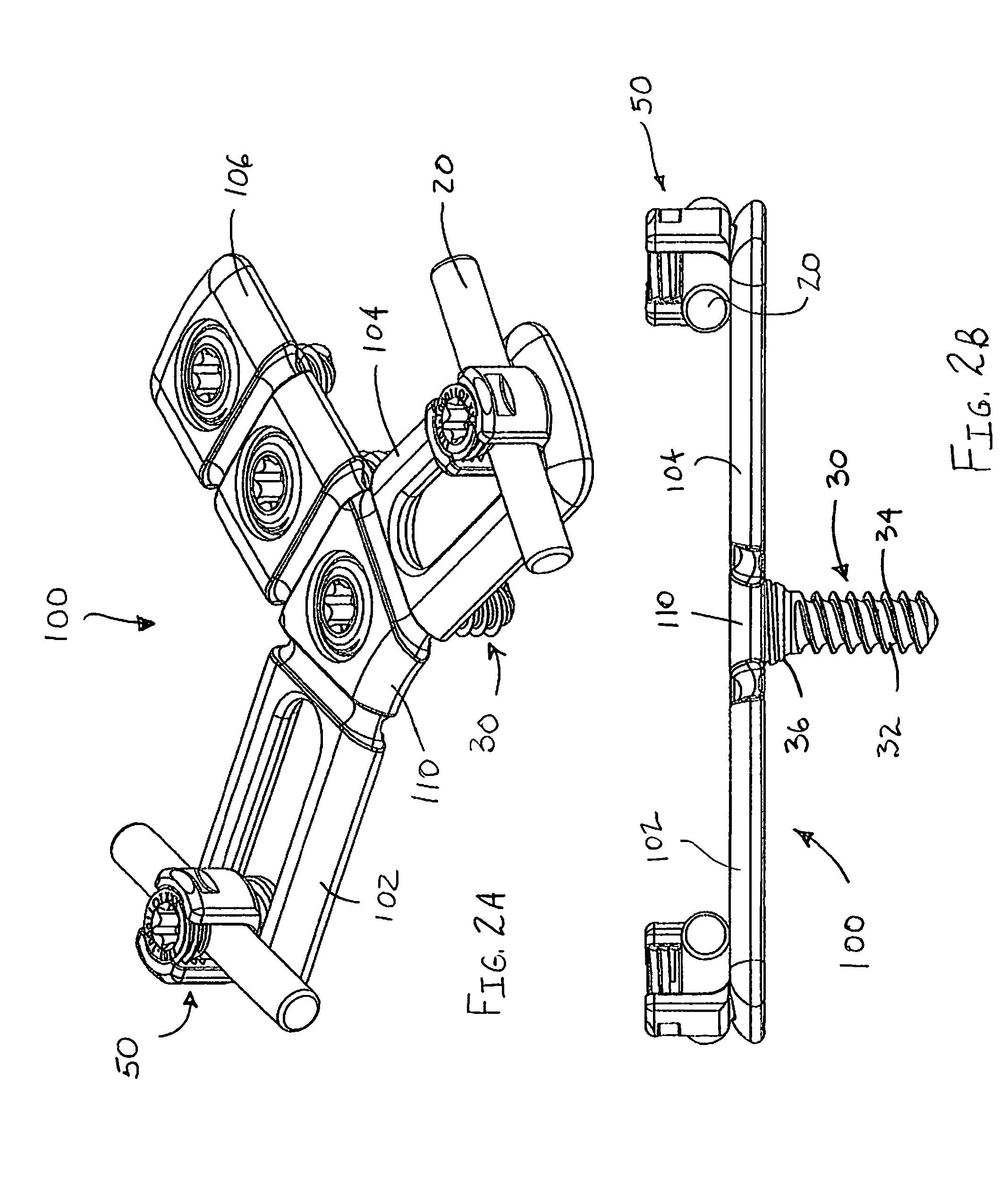
[0019]Various embodiments of the presently disclosed occipital plate for cervical fixation will now be described in detail with reference to the drawings, wherein like reference numerals identify similar or identical elements. In the drawings and in the description that follows, the term “proximal,” will refer to the end of a device or system that is closest to the operator, while the term “distal” will refer to the end of the device or system that is farthest from the operator. In addition, the term “cephalad” is used in this application to indicate a direction toward a patient's head, whereas the term “caudad” indicates a direction toward the patient's feet. Further still, for the purposes of this application, the term “medial” indicates a direction toward the middle of the body of the patient, whilst the term “lateral” indicates a direction toward a side of the body of the patient (i.e. away from the middle of the body of the patient). The term “posterior” indicates a direction t...


PUM


Abstract

An adjustable occipital plate includes a central body portion having a plurality of arms extending therefrom in a generally Y-shaped configuration. Two of the arms include elongate slots for slidably receiving retaining members therein. Each retaining member includes a U-shaped channel for receiving a spine rod and a set screw. The central body portion and one arm include openings for receiving bone screws therein. Each of the arms may be angled with respect to the central body portion.

Description

CROSS-REFERENCE TO RELATED APPLICATIONS[0001]This application claims priority to, and the benefit of, U.S. Provisional Patent Application Ser. No. 61 / 195,825, filed Oct. 10, 2008, the entire contents of which are hereby incorporated by reference.BACKGROUND[0002]1. Technical Field[0003]The present disclosure relates to devices for bone fixation. More particularly, the present disclosure relates to an occipital plate for cervical fixation.[0004]2. Background of Related Art[0005]The occipitocervical junction, which comprises the occiput, atlas, and axis, represents a unique and complex interface between the cranium and the rostral cervical spine. More than 50% of the rotation and flexion-extension of the head and neck occurs in that region. In addition, the osseous articulations and their ligamentous support structures must resist force in eight axes of rotation. These include flexion, extension, bilateral lateral bending; and bilateral rotation, distraction, and axial loading. Instrum...

Claims


Application Information

Patent Timeline
Patent Type & Authority Applications(United States)
IPC IPC(8): A61B17/80
CPCA61B17/7055A61B17/7044
Inventor HAGGENMAKER, JENNIFERKOSTUIK, JOHNBROWN, STEVE A.
Owner K2M
Learn More