
Ambilight displaying arrangement

a technology of ambilight and pixel arrangement, which is applied in the field of ambilight tv, can solve the problems of adding to the overall cost and dark area between the pixels, and achieve the effect of prolonging the immersive viewing experience for the viewer

Inactive Publication Date: 2010-04-15
TP VISION HLDG
View PDF3 Cites 24 Cited by
  • Summary
  • Abstract
  • Description
  • Claims
  • Application Information

AI Technical Summary

Benefits of technology

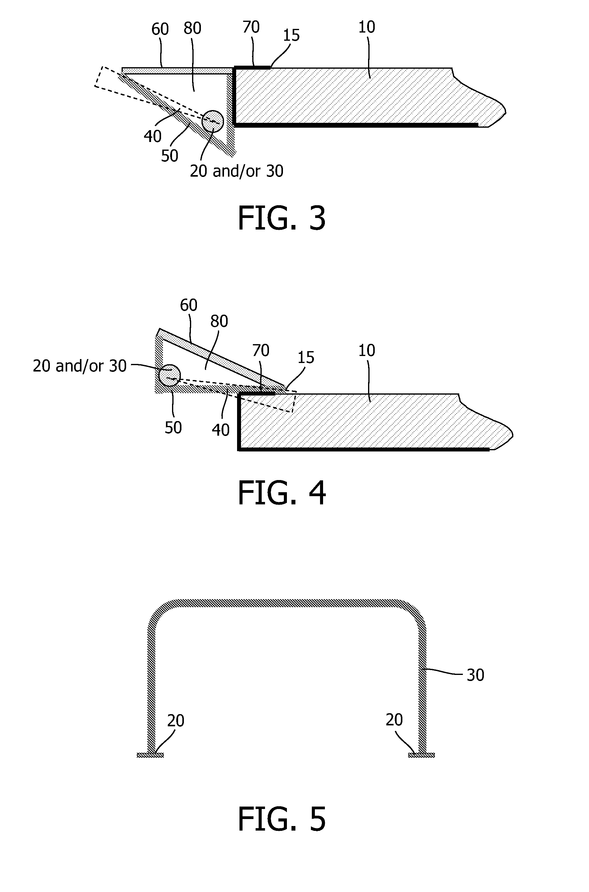
[0006]It may be seen as an object of the present invention to further enhance the viewing of video image(s) on the display screen. According to the present invention, this can be achieved by directly or / and indirectly illuminating the dark area between the pixel area of the display screen and the front of the lighting or illumination system (e.g. the pixel area of the display screen and the bezel or the diffuser), thus covering with illumination the area of the panel rim.
[0007]It may also be seen as an object of the invention to further simplify and economize the AmbiLight TV concept. According to the invention, this can be achieved by providing the display system with at least one U-shaped light guide, the legs of the light guide spatially corresponding to respective sides of the display screen. Herewith it is achieved that three sides of the display screen can be illuminated with only two light sources (preferably LEDs), one at each end of the U. This requires a very simple infrastructure for the overall system, thus reducing the costs tremendously. It is believed that the attractive AmbiLight TV feature will thus be made affordable in the lower TV, display and / or monitor segments.
[0009]Alternatively or additionally, in another possible embodiment the light sources can be arranged to radiate light to the front of the displaying arrangement. This is referred to as AmbiLight with bezel illumination. It creates an aura closer around the screen and it is more visible in environments with brighter illumination. Besides that it makes AmbiLight possible for devices that are not in the proximity of a wall to reflect the light, like monitors.

Problems solved by technology

One limitation of the current AmbiLight solutions is that there is a dark area between the pixel area of the display screen and the front of the lighting or illumination system, e.g. between the pixel area of the display screen and the bezel or the diffuser of said lighting or illumination system.
Another limitation of the current AmbiLight solutions is that each side is considered to have an individual lighting or illumination system, either a light guide or a light source (LED) array.
A full surround system will then comprise of 4 individual lighting or illumination systems with their own electrical and mechanical infrastructures adding up to the overall cost.

Method used


Image

  • Ambilight displaying arrangement
  • Ambilight displaying arrangement
  • Ambilight displaying arrangement

Examples


Embodiment Construction

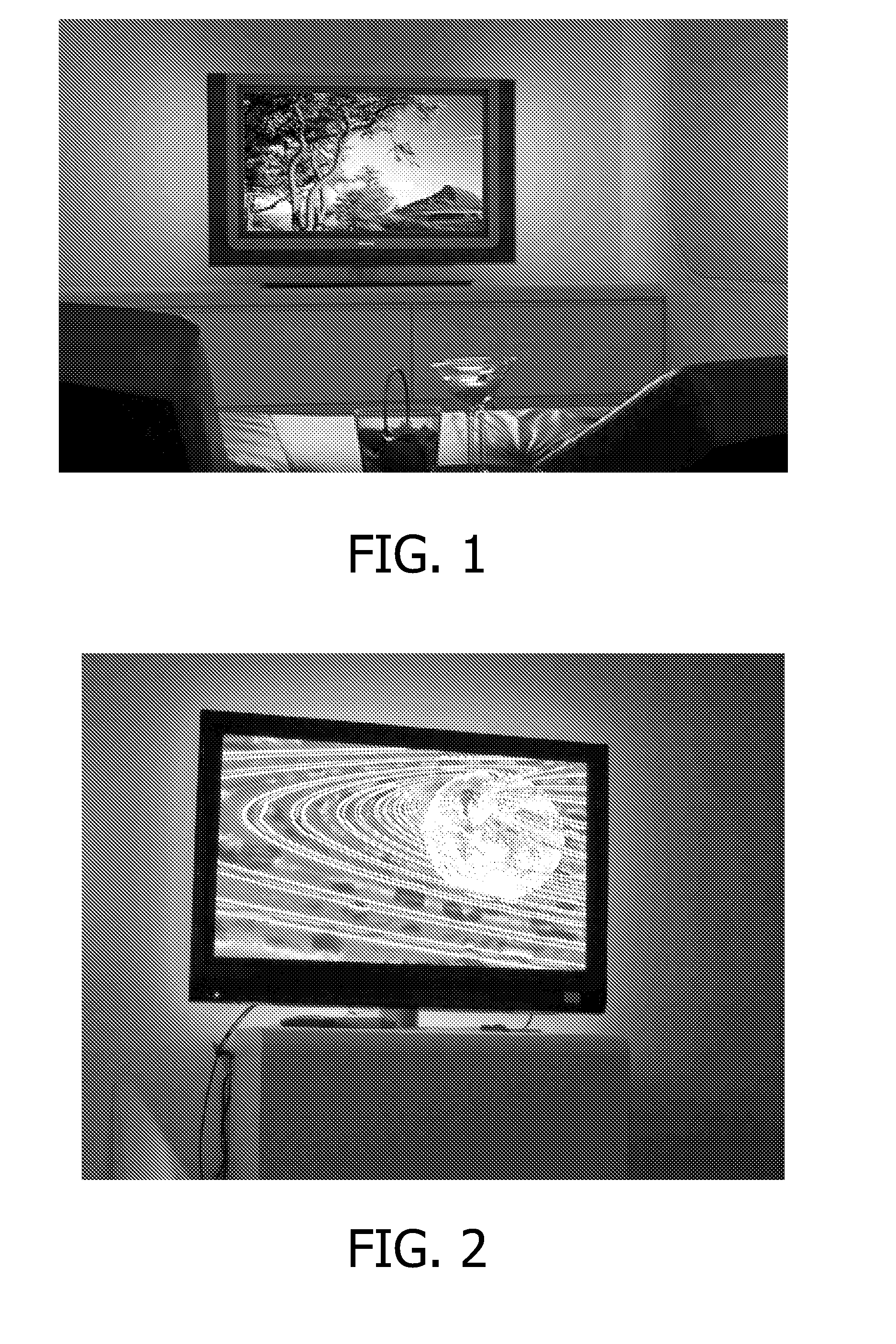
[0026]FIG. 1 shows an existing version of AmbiLight TV providing illumination to the left and right side.

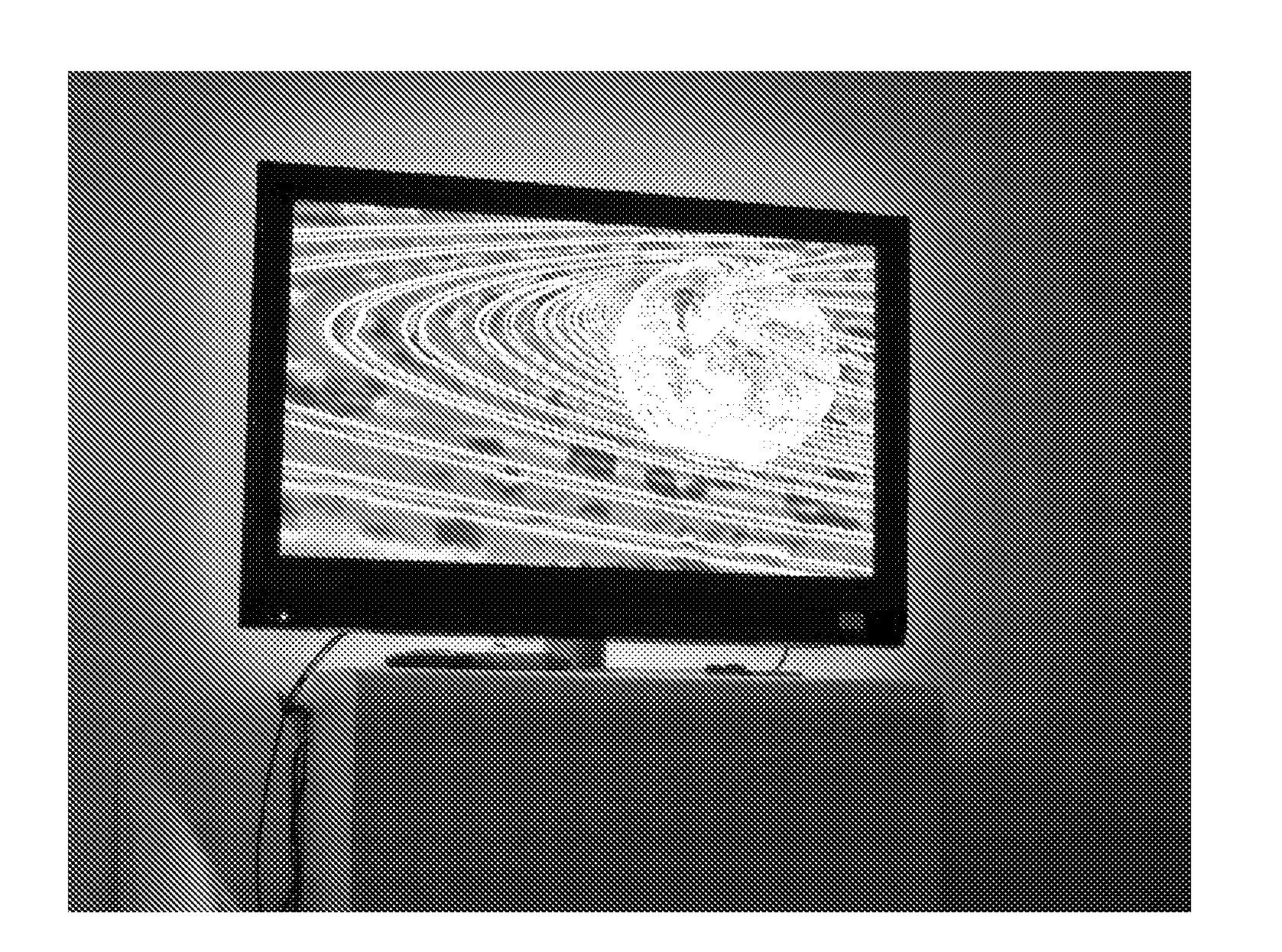
[0027]A “full surround” AmbiLight TV system is shown in FIG. 2. In this case all sides of the displaying arrangement are surrounded by the lighting or illumination system.

[0028]The displaying arrangement can be any TV, monitor, display, screen or any other suitable arrangement on which image(s) can be displayed and / or projected.

[0029]The invention can be based on the principles of a linear light guide, e.g. a massive PMMA tube, with a pattern (e.g. a scattering pattern, etc.) on it to get light out of the light guide in a controlled manner. The principle of light guide is well known. A point light source transmits into a transparent material with a highly reflective (polished) surface. This material is either painted with a white pattern or mechanically indented to have light emitted in a controlled manner in a desired direction and with a desired beam shape.

[0030]A display devic...


PUM


Abstract

Disclosed are embodiments of AmbiLight TV, a lighting or illumination system that has been introduced to enhance viewing experience. The system comprises one or two U-shaped light guides, the legs of which spatially correspond to three or four sides of the display screen. In one embodiment, the light sources illuminate a background surface behind the TV such as a wall. In another embodiment, the light sources are arranged around the display screen in substantially the same planar area, and radiate light to the front. In yet another embodiment, the light sources are arranged to directly or / and indirectly illuminate the dark area between the pixel area of the display screen and the front of the lighting or illumination system.

Description

FIELD OF THE INVENTION [0001]In the recent past, the company Philips introduced AmbiLight TV, a television receiver provided with rear light sources to illuminate the wall behind the TV. By automatically adapting the color of the light to the contents of the video image, AmbiLight offered a more immersive viewing experience to the viewer. An initial version of AmbiLight TV provided illumination of the left and right side with one color per side. Later generations were fitted with top and bottom light sources, still with one color per side.BACKGROUND OF THE INVENTION[0002]The AmbiLight solutions introduced by the company Philips in the recent past have enjoyed an enormous success around the world. However, due to the tremendous and increasing variety of viewer requirements, desires and demands, it is necessary to further develop the existing AmbiLight solutions and / or create new ones.[0003]The present invention seeks to further satisfy the fastidious viewer.SUMMARY OF THE INVENTION[0...

Claims


Application Information

Patent Timeline
Patent Type & Authority Applications(United States)
IPC IPC(8): H04N9/74H04N5/66
CPCG02B6/001H04N9/73H04N5/58G06F3/147G09G2354/00
Inventor HOOGENSTRAATEN, WILLEM FRANCISCUS JOHANNESVAN ASSELDONK, JOHANNES PETRUS ANTONIUS MARIA
Owner TP VISION HLDG
Learn More