
Control device

Inactive Publication Date: 2010-04-01
DENSO CORP
View PDF9 Cites 210 Cited by
  • Summary
  • Abstract
  • Description
  • Claims
  • Application Information

AI Technical Summary

Benefits of technology

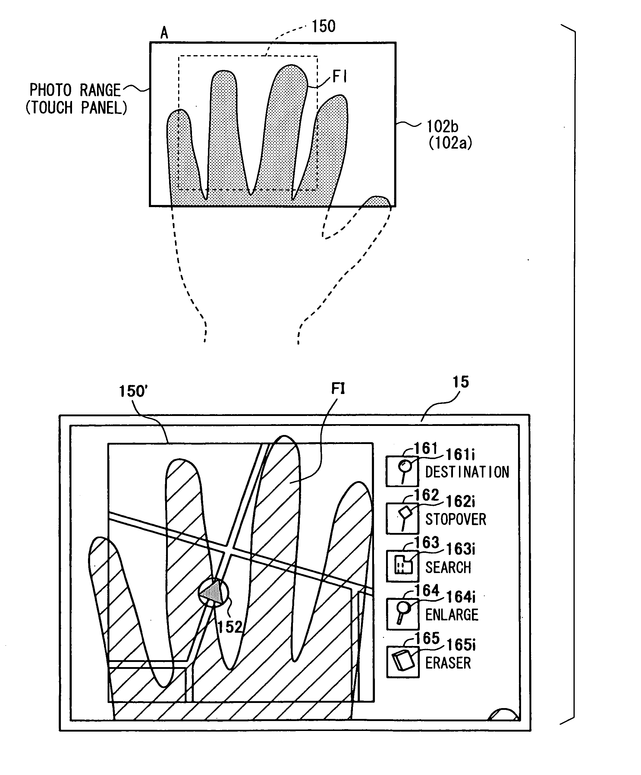
[0013]In view of the above and other points, it is an objective of the present invention to provide a control device capable of effectively using information on a captured image as input information and thereby capable of considerably extending an input form. For example, the control device may be configured to display a pointer image indicative of the present position of a fingertip and a move target image so that the pointer image and the move target image are movable together even when a finger of a user is spaced apart from a manipulation surface of a touch input device.
[0015]According to the above control device, it is possible to utilize information on position of the fingertip of the user based on the image of the hand even when the finger is being spaced apart from the manipulation surface. The control device can detect the position of the fingertip and the input location of the touch manipulation independently from each other. It is therefore possible to effectively use information on a captured image as input information and thereby possible to considerably extend an input form. For example, the control device enables input operation such as drag operation on an image item and the like in an intuitive manner based on the captured image.
[0017]According to the second aspect, the control device including the manipulation input element and the imaging device can generates and outputs the operation input information directed to the in-vehicle electronic apparatus based on the calculated value of the hand image area ratio and the manipulation state of the manipulation input region. Thus, as input information, it is possible to efficiently use information on the image captured by the imaging device in addition to the input information provided from the manipulation input element. Therefore, it is possible to largely extend input forms in utilizing the control device.

Problems solved by technology

In such a case, the operating devices typically do not allow the manipulation of continuous movement of a finger while the finger is being in contact with the input surface, because an error input can easily occur in the continuous movement.
In a case of a touch input device however, although a user can switch a target item into a selected state and specify a destination by performing a touch manipulation, when the user spaces a finger apart from a touch manipulation surface, the touch input device cannot detect finger position and cannot monitor a drag movement trajectory.
As a result, the operating device cannot display the movement of the target item in accordance with a movement trajectory of fingertip.

Method used


Image

  • Control device
  • Control device
  • Control device

Examples


first embodiment

Aspects of First Embodiment

[0183]The first embodiment and modification have the following aspects.

[0184]According to an aspect, there is provided a control device including: a touch input device that has a manipulation surface adapted to receive a touch manipulation made by a finger of a user, and detects and outputs an input location of the touch manipulation; an imaging device that has a photographing range having one-to-one coordinate relationship to the manipulation surface, and captures an image of a hand of the user getting access to the manipulation surface; a fingertip specifying section (or means) that specifies a fingertip of the hand based on data of the image of the hand; a display device that includes a display screen having one-to-one coordinate relationship to the photographing range and the manipulation surface; a pointer image display control section (or means) that causes the display device to display a pointer image on the display screen, the pointer image pointin...

second embodiment

Aspects of Second Embodiment

[0261]The second embodiment and it modifications have the following aspects.

[0262]According to an aspect, there is provided a control device for a user to operate an in-vehicle electronic apparatus in a vehicle by manipulating the control device. The control device includes: a manipulation input element that is located so as to be within reach of the user who is sitting in a seat of the vehicle, and that has a manipulation input region having a predetermined area; an imaging device that has a photographing range covering the manipulation input region, and that captures an image including a hand image region representative of the hand of the user getting access to the manipulation input element; a hand image region identification section that identifies the hand image region in the image; an area ratio calculation section that calculates a value of hand image area ratio, which is area ratio of the hand image region to the manipulation input region; and an ...


PUM


Abstract

There is provided a control device for an in-vehicle electronic apparatus. The control device includes: a manipulation input element that has a manipulation input region having a predetermined area; an imaging device that has a photographing range covering the manipulation input region, and that captures an image including a hand image region representative of the hand; a hand image region identification section that identifies the hand image region in the image; an area ratio calculation section that calculates a value of hand image area ratio, which is area ratio of the hand image region to the manipulation input region; and an operation input information generation section that generates and outputs operation input information based on the calculated value of the hand image area ratio and a manipulation state of the manipulation input region, the operation input information being directed to the in-vehicle electronic apparatus.

Description

CROSS REFERENCE TO RELATED APPLICATION[0001]The present application is based on Japanese Patent Applications No. 2008-251783 filed on Sep. 29, 2008 and No. 2009-020635 filed on Jan. 30, 2009, disclosures of which are incorporated herein by reference.BACKGROUND OF THE INVENTION[0002]1. Field of the Invention[0003]The present invention relates to a control device, more particularly to a control device for an in-vehicle apparatus.[0004]2. Description of Related Art[0005]There has been proposed various types of control device for an in-vehicle apparatus such as a car navigation apparatus and the like. One type of such control device is an operating device that captures an image of a hand of a user, extracts a finger image from the captured image, and superimposes the extracted finger image on a GUI input window such as a navigation window and the like of the in-vehicle apparatus.[0006]For example, Patent Document 1 discloses an operating device that uses a camera mounted to a ceiling of...

Claims


Application Information

Patent Timeline
IPC IPC(8): G06F3/042G06F3/048G01C21/32G06F3/041
CPCB60K35/00B60K37/06B60K2350/1004G01C21/3664G06F3/0483G06F3/0425G06F3/04883G06F3/04886G06F2203/04808G06F3/0416B60K35/10B60K2360/11
Inventor KAWASHIMA, TAKESHIITOH, MASAHIRO
Owner DENSO CORP
Learn More