Eureka AIR delivers breakthrough ideas for toughest innovation challenges, trusted by R&D personnel around the world.

Apparatus including a pin connector for securing a first member and a second member to one another, and associated methods

Active Publication Date: 2010-03-18
BAL SEAL ENG CO INC
View PDF14 Cites 7 Cited by
  • Summary
  • Abstract
  • Description
  • Claims
  • Application Information

AI Technical Summary

Benefits of technology

[0005]The preferred embodiments of the present apparatus and methods for securing a first member and a second member to one another have several features, no single one of which is solely responsible for their desirable attributes. Without limiting the scope of the present embodiments as expressed by the claims that follow, their more prominent features now will be discussed briefly. After considering this discussion, and particularly after reading the section entitled “Detailed Description of the Preferred Embodiments,” one will understand how the features of the present embodiments provide advantages, which include reliable securement of members, and the capacity to quickly connect and disconnect members.

Problems solved by technology

One disadvantage of threaded fasteners is that advancing a male threaded member into a female threaded hole (and withdrawing it therefrom) requires a relative twisting of the threaded members.
This twisting is time consuming and can be difficult to perform in hard to reach places.
The time factor becomes severely limiting in applications where a large number of fasteners must be removed in order to disassemble objects, and / or where the fasteners must be frequently removed and replaced.
However, these components are generally not able to tolerate any variations in thickness.

Method used


Image

  • Apparatus including a pin connector for securing a first member and a second member to one another, and associated methods
  • Apparatus including a pin connector for securing a first member and a second member to one another, and associated methods
  • Apparatus including a pin connector for securing a first member and a second member to one another, and associated methods

Examples


Embodiment Construction

,” one will understand how the features of the present embodiments provide advantages, which include reliable securement of members, and the capacity to quickly connect and disconnect members.

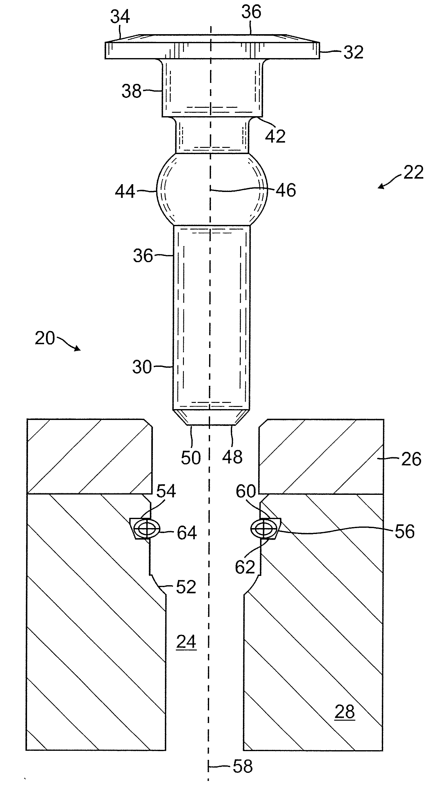
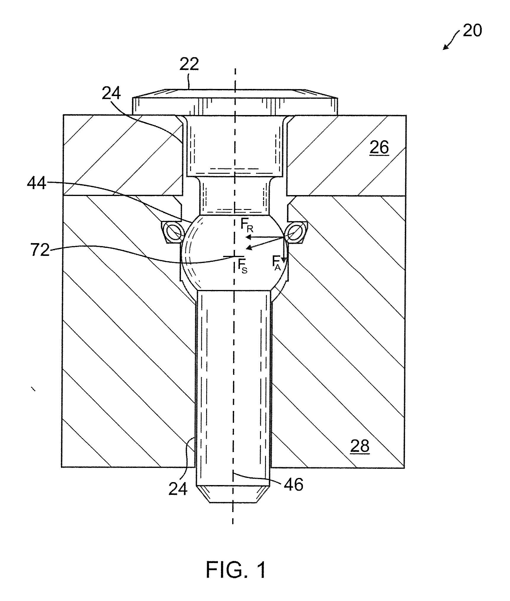
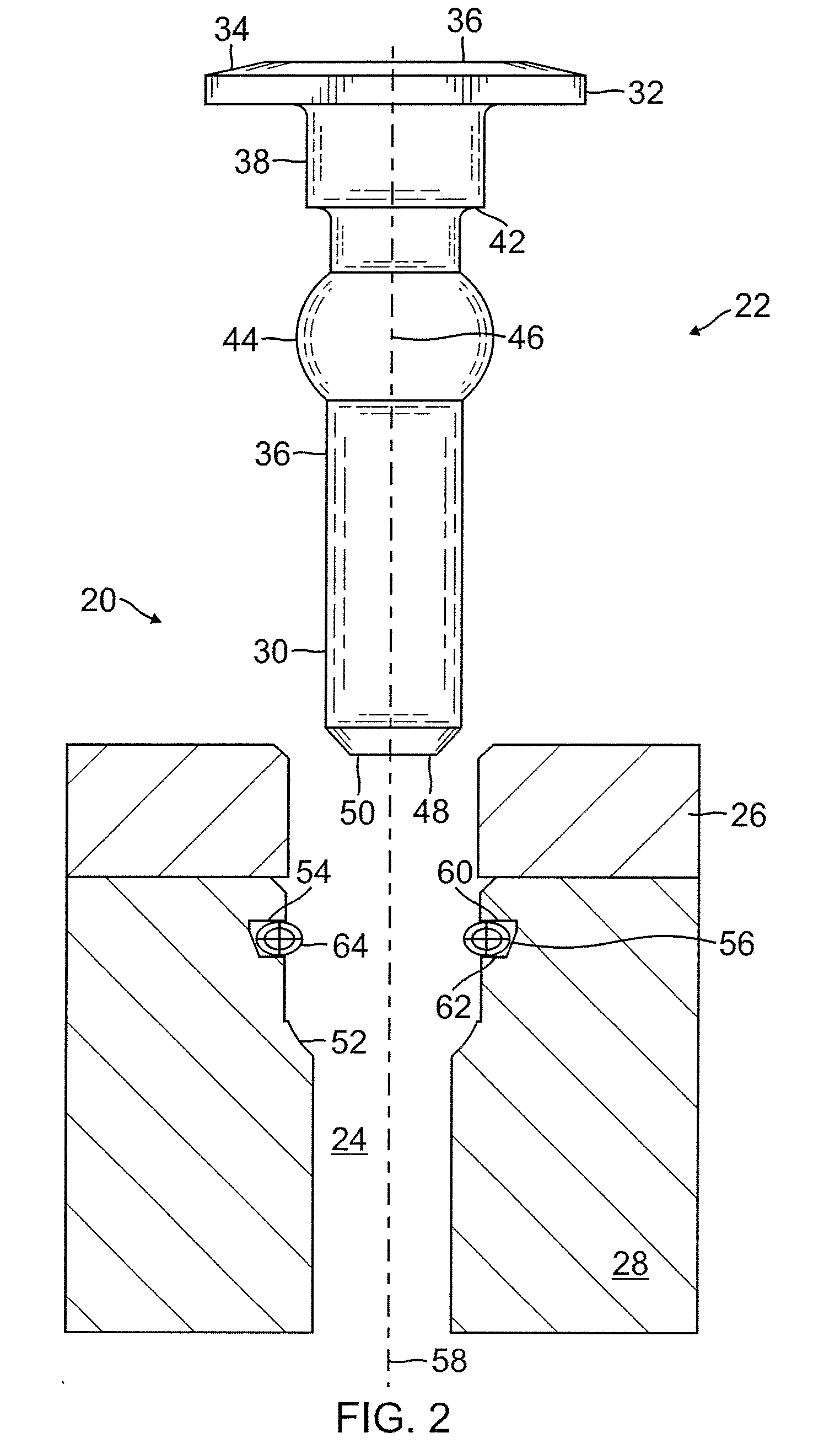
[0006]One embodiment of the present apparatus is configured for securing a first member and a second member to one another. The first and second members include a bore extending through at least one of the first and second members and at least partially through the other of the first and second members. The apparatus comprises a pin connector including a head portion having a first diameter. The pin connector further includes an elongate, unthreaded shank extending from the head portion. The shank has at least a first portion with a second diameter that is less than the first diameter. The pin connector further includes an enlarged ball portion positioned along the shank. The ball portion is shaped substantially as a double-truncated sphere and has a third diameter that is less than the first d...


PUM

PropertyMeasurementUnit
Thicknessaaaaaaaaaa
Forceaaaaaaaaaa
Diameteraaaaaaaaaa

Abstract

Embodiments of the present apparatus are configured to secure a first member and a second member to one another. The first and second members include a bore extending through at least one of the first and second members and at least partially through the other of the first and second members. The apparatus comprises a pin connector including an enlarged ball portion positioned along a shank. The first member includes an annular groove extending around the bore. A canted coil spring seats within the groove. The apparatus is configured such that the spring exerts a squeezing force on the ball portion when the pin connector is disposed within the bore and the head of the pin connector contacts the second member.

Description

CROSS-REFERENCE TO RELATED APPLICATION[0001]This is a regular utility application of provisional application No. 61 / 097,076, filed Sep. 15, 2008, the contents of which are expressly incorporated herein by reference for all purposes.FIELD OF ART[0002]The present invention relates to connectors for securing objects together.DESCRIPTION OF RELATED ART[0003]Male threaded fasteners, such as screws and bolts are commonly used to secure objects together. One advantage of threaded fasteners is that they can tolerate variations in thickness in one or both of the objects to be secured together. The threaded member can be advanced into a threaded hole in one of the objects, or in a nut, until the desired tension is achieved.[0004]One disadvantage of threaded fasteners is that advancing a male threaded member into a female threaded hole (and withdrawing it therefrom) requires a relative twisting of the threaded members. This twisting is time consuming and can be difficult to perform in hard to ...

Claims


Application Information

Patent Timeline
IPC IPC(8): A44B99/00
CPCF16B19/02F16B19/109F16B21/06F16B21/20Y10T24/4691Y10T24/45848Y10T29/49876Y10T24/45099Y10T24/42Y10T24/46
Inventor BALSELLS, PETE
Owner BAL SEAL ENG CO INC
Why Eureka
Eureka Blog
Learn More