Led rescue light

a technology of led rescue light and led battery, which is applied in the direction of visible signalling system, instruments, signalling system, etc., can solve the problems of limited light that can be produced with a fixed battery power source, large battery is not practical in a rescue application, and the need for hemispheric coverage cannot be satisfied, so as to achieve the effect of preserving battery li

Inactive Publication Date: 2010-03-11
REVERE SUPPLY
View PDF10 Cites 2 Cited by
  • Summary
  • Abstract
  • Description
  • Claims
  • Application Information

AI Technical Summary

Benefits of technology

The patent text describes a solution to a problem where a device's battery life is quickly depleted when it constantly flashes. The solution involves driving the LED with a lot of current for a short period of time, and then stopping the flashing using a switch. The text also describes a novel way of controlling the flashing using a movable member of the device. The technical effect of this solution is to conserve battery life while still achieving the desired flashing effect.

Problems solved by technology

The technical problem addressed in this patent text is the need for a small battery-powered rescue light that can produce a minimum intensity of 0.75 candela over the entire hemisphere for at least 8 hours, using no more than two batteries of the AA size or a single 3 Volt battery. The challenge is to balance the intensity and duration of the light while using LEDs that can meet the minimum requirements for brightness with small batteries.

Method used


Image

  • Led rescue light
  • Led rescue light
  • Led rescue light

Examples


Embodiment Construction

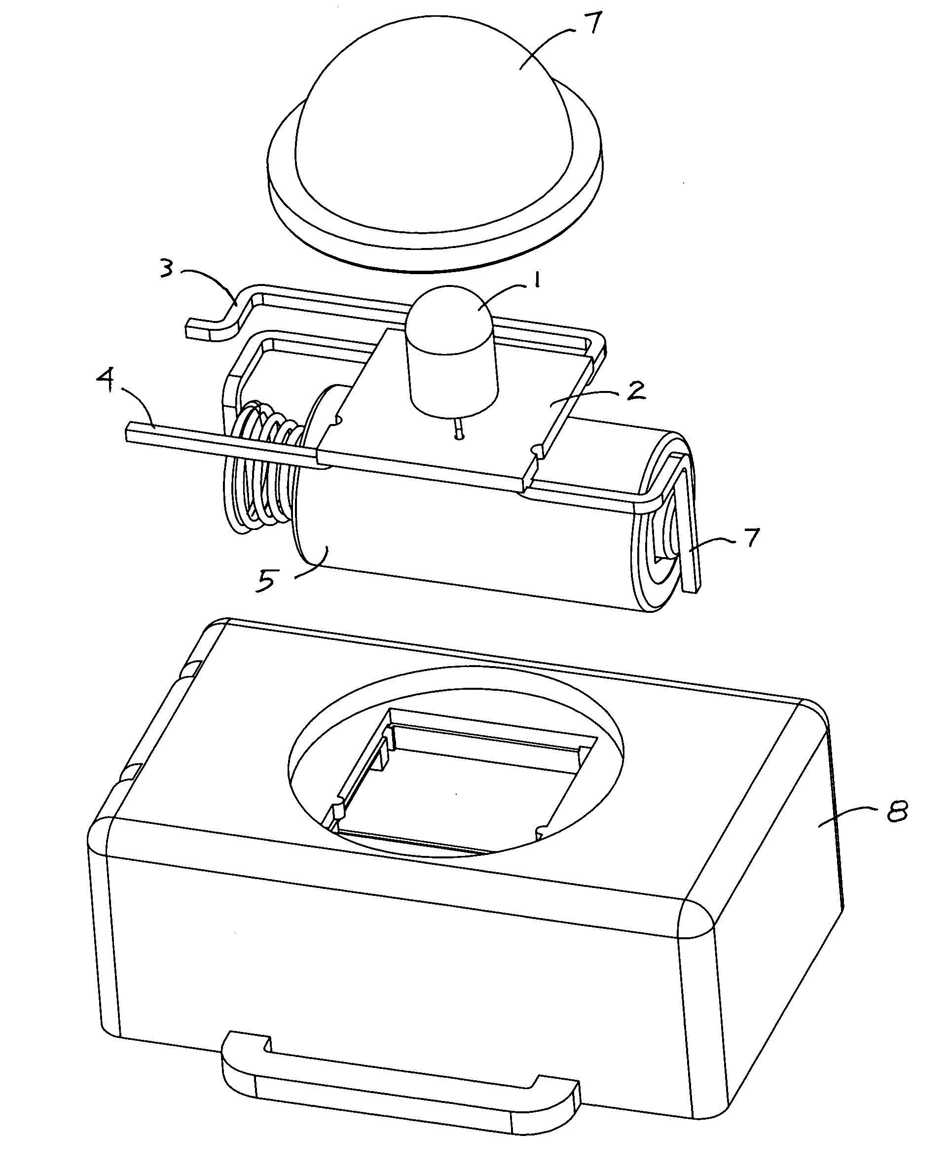
[0015]Referring now to FIG. 1, low power LED 1 is attached to circuit board 2 which is populated with a microprocessor and other electronic components designed to create a water sense circuit and a Voltage boost circuit which is used to supply operating Voltage and regulated current to LED 1. Connectors 6 and 7 are used to connect battery 5 to circuit board 2. Connectors 3 and 4 are positioned to be connected to the water sense circuit on circuit board 2 and any water present outside the walls of housing 8. Circuit board 2, LED 1, battery 5, and connectors 3, 4, 6, and 7 are contained inside housing 8 and held in place by cover 7.

[0016]In operation, whenever water sense connectors 3 and 4 come in contact with water, the water sense circuit send a signal to the boost circuit causing LED 1 to be energized. As long as water is present, LED 1 will continue to be energized. If the water is removed, LED 1 will be turn off in a few minutes and circuit board 2 will enter a sleep mode of ope...


PUM


Abstract

The present invention describes a rescue light with a LED light source that meets a minimum requirement of 0.75 candela (cd) of intensity, over a full hemisphere of visibility, with a duration of 8 hours or more. The invention requires only 3 volts of battery power from relatively small batteries, making the invention small and lightweight. In one favorite embodiment the LED is a specially constructed device that uses a blue LED die enclosed with a uniform layer of phosphor on the outer surface of the LED body, which provides an equally bright white light in all directions. Due to the low power requirements of the LED, the device can easily produce white light over an entire hemisphere at the required brightness level for longer than the required amount of time. In another favorite embodiment, a power LED with a large viewing angle is powered with a relatively high current, so as to meet the requirements for intensity over the entire hemisphere, but the high current is applied for only short periods of time in order to meet the requirement for duration. In this second embodiment, a novel switching arrangement is provided to allow the user to turn the LED on and off by changing positions of a movable member of the device, where the original position of the movable member is independent of the operational state of the device. In a third favorite embodiment, multiple LEDs are incorporated for greater visibility, and the operational state of the device is changed by pressing a momentary switch. In all of the described embodiments, a water sensitive switch may be provided to activate the LED on contact with a body of water.

Description


Claims


Application Information

Patent Timeline
Owner REVERE SUPPLY
Why Eureka
Try Eureka