
System and method for ictal source analysis

a source analysis and source technology, applied in the field of source analysis, can solve the problems that traditional analysis methods involving eeg traces are poorly suited to disentangle measured pathological activity

Inactive Publication Date: 2010-02-25
RGT UNIV OF MINNESOTA
View PDF4 Cites 27 Cited by
  • Summary
  • Abstract
  • Description
  • Claims
  • Application Information

AI Technical Summary

Problems solved by technology

Traditional analysis methods involving inspection of EEG traces are poorly suited to disentangle measured pathological activity.

Method used


Image

  • System and method for ictal source analysis
  • System and method for ictal source analysis
  • System and method for ictal source analysis

Examples


Embodiment Construction

Preliminaries

[0070]The following detailed description includes references to the accompanying drawings, which form a part of the detailed description. The drawings show, by way of illustration, specific embodiments in which the invention can be practiced. These embodiments are also referred to herein as “examples.” The embodiments can be combined, other embodiments may be utilized, or structural, logical and electrical changes can be made without departing from the scope of the present invention. The following detailed description is, therefore, not to be taken in a limiting sense, and the scope of the present invention is defined by the appended claims and their equivalents.

[0071]In this document, the terms “a” or “an” are used, as is common in patent documents, to include one or more than one, independent of any other instances or usages of “at least one” or “one or more.” In this document, the term “or” is used to refer to a nonexclusive or, such that “A or B” includes “A but not...


PUM


Abstract

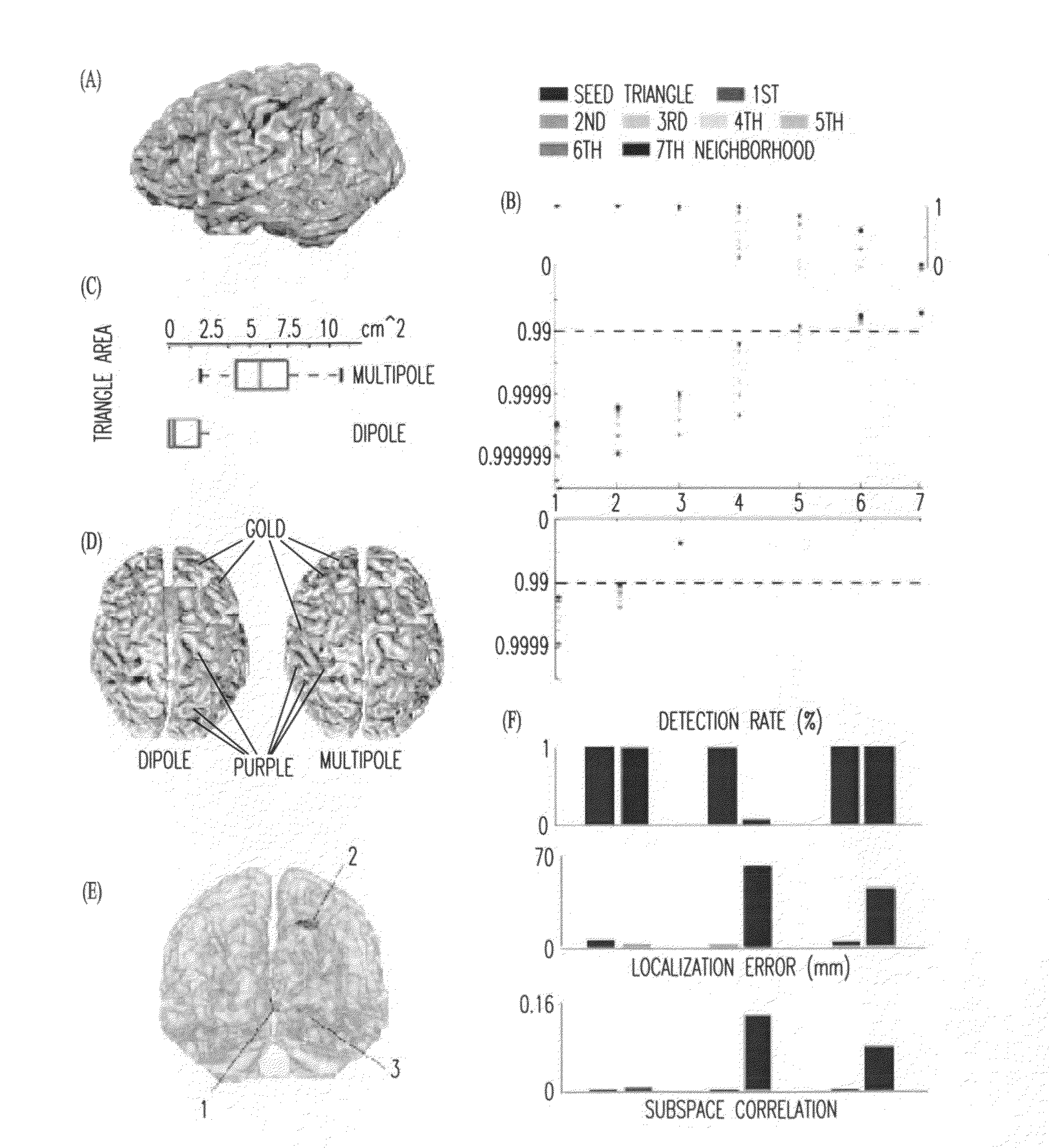
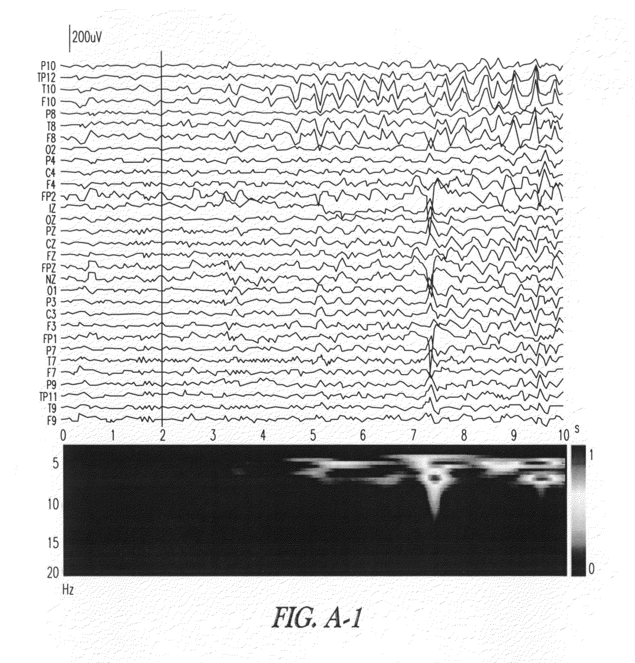
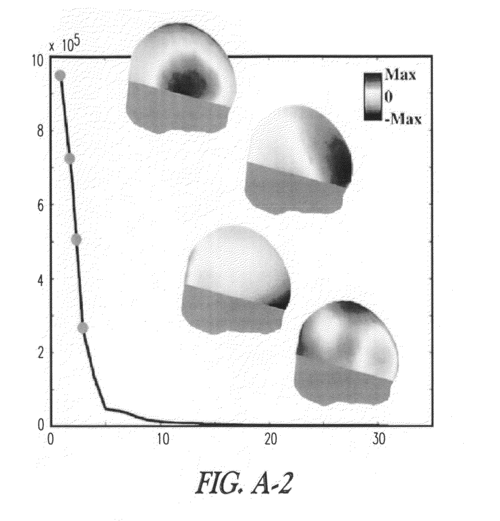
This document discloses, among other things, ictal source analysis and causal interaction estimation which considers the structure of seizures in the space, time, and frequency domains. The dynamic causal interaction can distinguish the primary source, which initiates the ictal activity, from the secondary source, which is generated due to the ictal activity propagation.

Description

CROSS-REFERENCE TO RELATED PATENT DOCUMENTSPriority of Invention[0001]This application is a Continuation Under 35 U.S.C. §1.111 (a) of International Application No. PCT / US2007 / 009638, filed Apr. 20, 2007 and published in English as WO 2007 / 124040 on Nov. 1, 2007, which claims the benefit of priority under 35 U.S.C. Section 119(e), to Bin He et al., U.S. Provisional Patent Application Ser. No. 60 / 793,989, entitled “METHOD AND APPARATUS OF ACTIVATION AND CAUSALITY IMAGING OF BIOELECTRICAL ACTIVITY,” filed on Apr. 21, 2006; which applications and publication are hereby incorporated by reference and made a part hereof.GOVERNMENT RIGHTS[0002]This invention was made with Government support under Grant Numbers R01-EB00178 awarded by the National Institutes of Health, and under Grant Number BES-0411898, awarded by the National Science Foundation. The Government has certain rights in this invention.TECHNICAL FIELD[0003]This document pertains generally to source analysis, and more particularl...

Claims


Application Information

Patent Timeline
IPC IPC(8): G06F17/11
CPCA61B5/4094A61B5/048A61B5/374
Inventor HE, BINDING, LEILAI, YUAN
Owner RGT UNIV OF MINNESOTA
Learn More