Clip package and clip loading method

Inactive Publication Date: 2010-02-25
FUJIFILM CORP
View PDF6 Cites 10 Cited by
  • Summary
  • Abstract
  • Description
  • Claims
  • Application Information

AI Technical Summary

Benefits of technology

[0014]An objection of the present invention is to provide a clip package that eliminates the above problems and permits distribution and storage with an endoscopic clip and a connection ring coupled to each other, easy loading into the sheath of the endoscopic clip while keeping such connection, and easy application to also a clipping device that performs successive clipping.

Problems solved by technology

Thus, the conventional clipping device involves a rather bothersome operation.
However, the clip case proposed in JP 2007-222649A had a problem: retraction of the projections into the holder tube is achieved by abutting the projections of the clip holder tube against the slant portion formed close to the exit of the clip case, whereas the direction in which the projections are inclined with respect to the clip's moving direction is opposite to the direction in which the slant portion is formed, thus placing a load upon the projections (skirt portion) and possibly breaking the projections.
However, since the clip case described in JP 2007-222649A houses only one clip, the clip case described in JP 2007-222649A cannot be applied to the clipping device described in JP 2006-187391A.

Method used


Image

  • Clip package and clip loading method
  • Clip package and clip loading method
  • Clip package and clip loading method

Examples


first embodiment

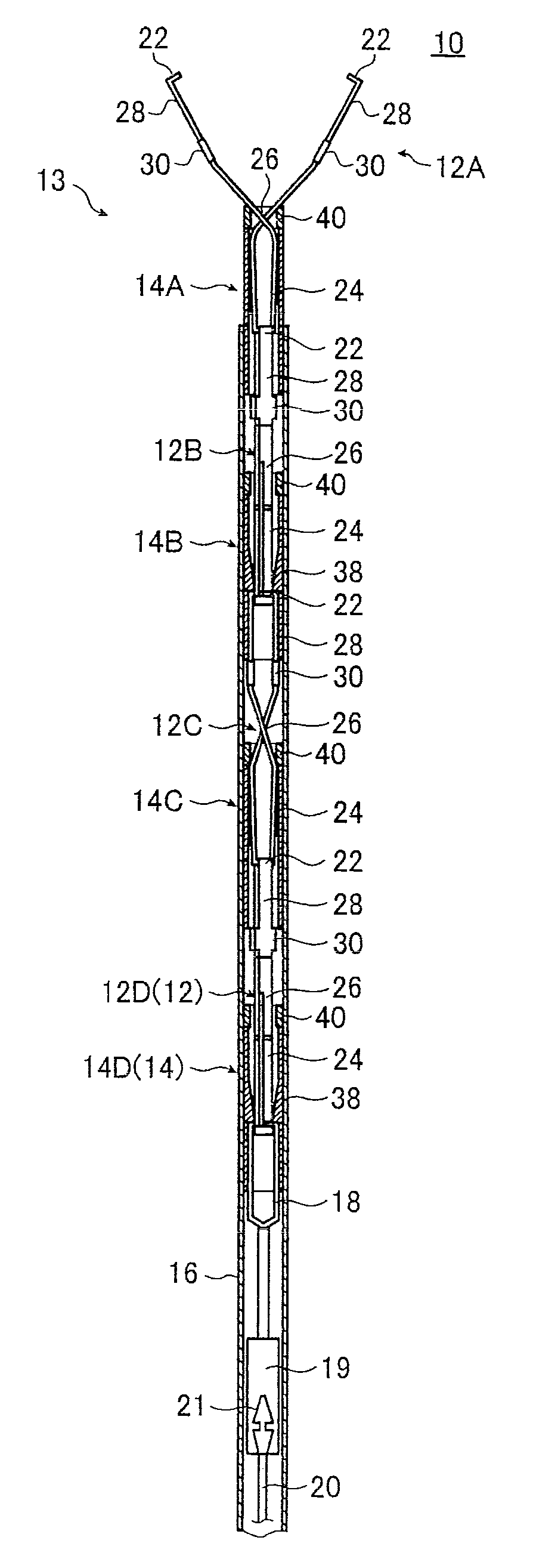
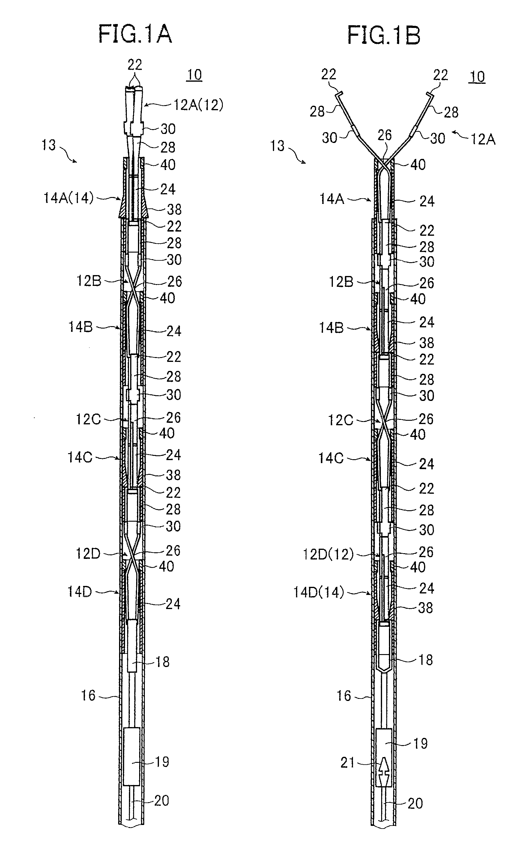
[0141]FIGS. 6A through 6C are a side view, a side sectional view, and a front sectional view, respectively, illustrating a connected clip package according to a first embodiment. In the following description, the left end is referred to as a forward end and the right end is referred to as a proximal end in FIGS. 6A and 6B.

[0142]The above description of the clipping device 10 has been made referring to an example comprising four connected clip units. The description below will be made by way of an example comprising five connected clip units.

[0143]As illustrated in FIG. 6A, a successive clip package 80 comprises a case 82, an upper cap 84, a lower cap 86, and an outer tube 89.

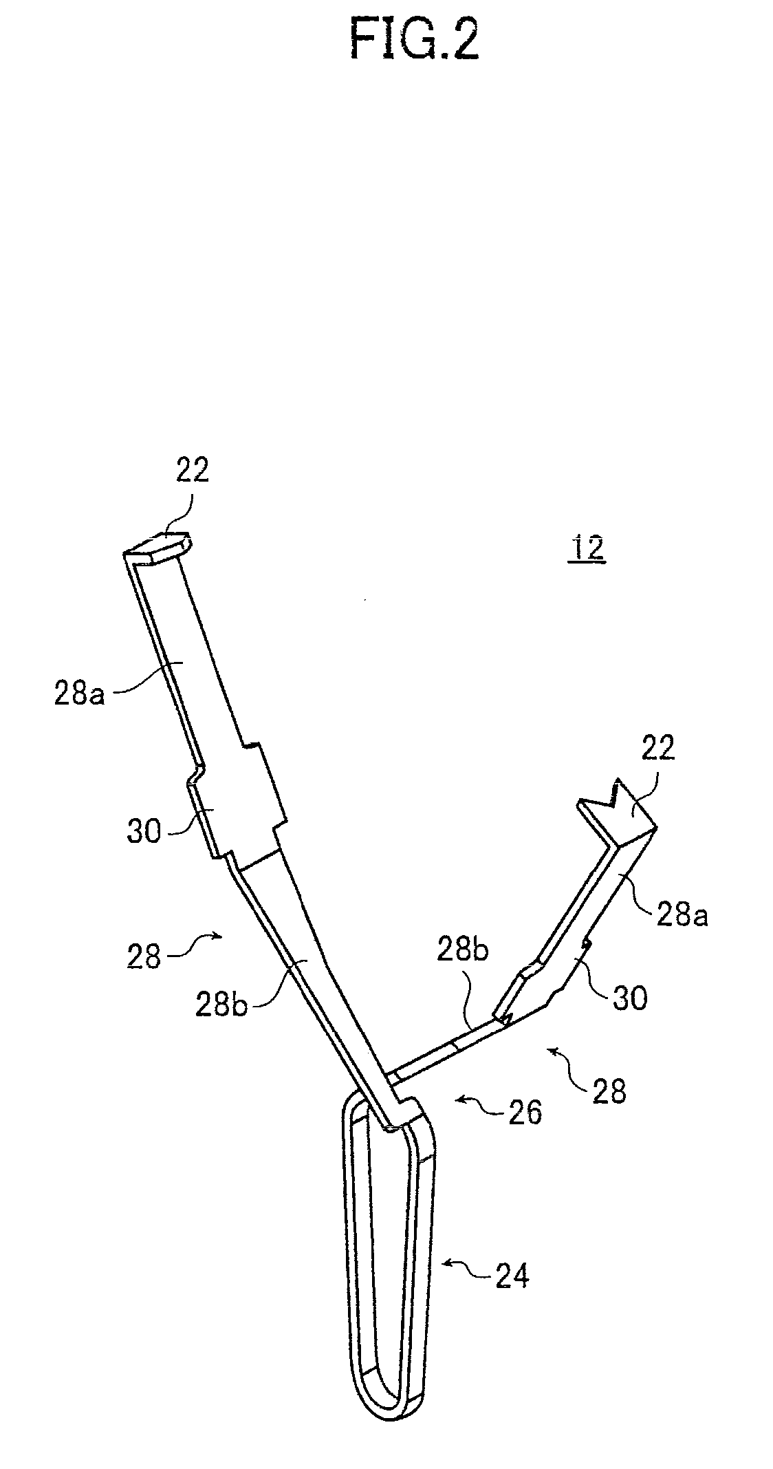
[0144]The case 82 has a cylindrical shape and contains clip units each comprising a clip 12 and a connection ring 14. As illustrated in FIGS. 6A and 6C, the case 82 is formed of two case parts (upper and lower halves) 82a and 82b each substantially semi-cylindrical and symmetrical with respect to the axis of the...

second embodiment

[0184]FIGS. 9A through 9C are a side view, a side sectional view, and a front sectional view, respectively, illustrating a connected clip package 100 according to a second embodiment.

[0185]The connected clip package 100 comprises a case 102, an outer tube 104, and an upper cap 84 and a lower cap 86.

[0186]The connected clip package 100 has guide grooves 112 formed in the outer periphery of the case 102 extending along the axis of the cylinder and passing through openings 110, thus forming apertures 114 at the openings 110. The outer tube 104 comprises guide ridges 116 and the projections 118. The guide ridges 116 are formed on the inner periphery of the outer tube 104 in positions corresponding to the guide grooves 112 and extend along the axis of the cylinder so as to engage with the guide grooves 112. The projections 118 are formed on the guide ridges 116 in positions corresponding to the openings 110 to engage with the apertures 114. The case 102 and the outer tube 104 otherwise h...

third embodiment

[0207]FIGS. 11A through 11C are a perspective view, a side sectional view, and a front sectional view, respectively, illustrating an outer tube 132 used for a connected clip package 130 according to a third embodiment. FIGS. 12A through 12B are cross sectional views illustrating the connected clip package 130.

[0208]The case used for the connected clip package 130 is the same as the case 82 illustrated in FIGS. 6A to 6C, and views and therefore descriptions thereof will not be given.

[0209]The outer tube 132 is a cylindrical member having substantially the same inner diameter as the outer diameter of the case and comprises apertures 134 formed in the regions corresponding to the openings 91.

[0210]As illustrated in FIGS. 12A and 12B, the connected clip package 130 has the case 82 housed inside the outer tube 132, that is to say, the outer periphery of the case 82 is covered with the outer tube 132, already from when it is in storage and distribution.

[0211]In storage and distribution, t...


PUM


Abstract

A clip package comprises: a clip assembly including at least one endoscopic clip and at least one connection ring connected to the clip, the connection ring having at least one skirt portion that is allowed to expand radially outwards and stick out when in natural state free from external force and closes inwards when depressed radially inwards, a cylindrical case including an accommodation section for accommodating the clip assembly, the cylindrical case further including at least one opening in a position corresponding to the skirt portion of the connection ring, the opening being provided to maintain the skirt portion in natural state, and a cylindrical outer tube movably fitted over the outer periphery of the case and including at least one skirt closer for depressing and inwardly closing the skirt portion when the skirt closer is moved to a position opposite the opening.

Description

BACKGROUND OF THE INVENTION[0001]The present invention relates to a package for distribution and storage of an endoscopic clip used for hemostasis, closure of a diseased part such as a wound, etc. in a living body or the like and, in particular, to a clip package for a successive clipping device that permits a successive use of clips.[0002]The present invention also relates to a method of loading the clip from the clip package into a sheath.[0003]An endoscopic clipping device is used to cause a clip to protrude from the tip of an endoscope inserted into a living body and pinch a bleeding site or a region to be treated after the removal of a lesion tissue, thereby achieving hemostasis, closure of a diseased part such as a wound, and the like. The conventional clipping device comprises a clip having open ends and a clamping portion for closing and placing the clip. Advancing the clamping portion in relation to the open clip closes the clip.[0004]For example, US 2002 / 0133178 A1 describ...

Claims


Application Information

Patent Timeline
IPC IPC(8): A61B17/06F16B2/20
CPCA61B17/1222A61B2017/0053A61B17/1285A61B17/1227
Inventor ITOH, KOJIIIDA, TAKAYUKIKUNUKI, YOSHIYUKI
Owner FUJIFILM CORP
Why Eureka
Try Eureka