
Power connector with integrated signal connector

a technology of power connectors and signal connectors, applied in the direction of connection formation by deformation, line/current collector details, coupling device connections, etc., can solve the problems of more expensive or difficult manufacture of such connectors than desired, and achieve the effect of improving the security of the mating connection, increasing the latch force, and increasing the latch for

Inactive Publication Date: 2010-02-18
MOLEX INC
View PDF5 Cites 40 Cited by
  • Summary
  • Abstract
  • Description
  • Claims
  • Application Information

AI Technical Summary

Benefits of technology

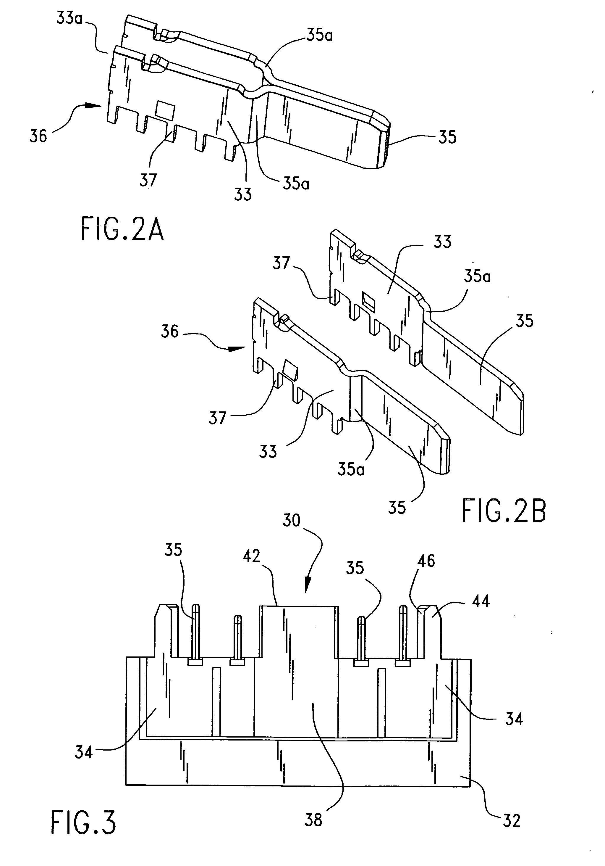
[0004]A connector assembly may be provided that includes a plug connector and a receptacle connector. The connector assembly includes one or more blade-type power contacts on the plug connector and multiple-pronged power contacts on the receptacle connector. The plug connector includes signal pin contacts mounted within a shrouded area of the module. The receptacle connector may include a signal module that is slidably mateable with the receptacle connector. When the plug connector and receptacle connector are joined, signal contacts in the signal module couple to signal pin contacts in the plug connector. In addition, power contacts on the plug connector engage power contacts the receptacle connector. Thus, the connector allows power and signals to be coupled together with a single connector assembly. If desired, a terminal position assurance member may be used to help secure the signal module and the power contact in place.
[0007]In another embodiment, an enhanced latch may be employed on the receptacle connector. The latch may have support ribs providing additional strength to the latches. This provides for increased latch forces to disengage the receptacle connector, thereby improving the security of the mating connection.

Problems solved by technology

While existing connectors have provided acceptable, certain aspects of existing designs make the manufacture of such connectors more costly or difficult than desired.

Method used


Image

  • Power connector with integrated signal connector
  • Power connector with integrated signal connector
  • Power connector with integrated signal connector

Examples


Embodiment Construction

[0036]As required, detailed embodiments of the present invention are disclosed herein; however, it is to be understood that the disclosed embodiments are merely exemplary of the invention, which may be embodied in various forms. Therefore, specific details disclosed herein are not to be interpreted as limiting, but merely as a basis for the claims and as a representative basis for teaching one skilled in the art to variously employ the present invention in virtually any appropriate manner, including employing various features disclosed herein in combinations that might not be explicitly disclosed herein.

[0037]One or more embodiments of the present disclosure can realize the benefit of providing separate power and signal housings that readily integrate into one common connector. Other benefits can include providing a common terminal position assurance member for both power and signal contacts. Another possible benefit is to provide a structure that strengthens latching on the connect...


PUM

PropertyMeasurementUnit
poweraaaaaaaaaa
current densityaaaaaaaaaa
forceaaaaaaaaaa

Abstract

A connector is provided that is suitable for connection to another connector. The connector can be a plug connector or a receptacle connector. The connector has a power contact and a signal contact. The signal contact may be provided by a modular housing that can be inserted into the connector housing. The signal contact can be wired separately into the modular housing and then the modular housing can be is inserted into the connector housing. A terminal position assurance member can then be used to secure the modular housing and power contact. An assembly of both the plug connector and the receptacle connector can be provided.

Description

BACKGROUND OF THE INVENTION[0001]The present invention generally relates to combined electrical power and signal connectors that are integrated into a connector system and that can provide excellent operation under high current density conditions.[0002]In general, connectors are suitable for use as modular components within modular assemblies. For example, modular assemblies can take, for example, the form of wire-to-board or wire-to-wire connectors and can, when desired, provide a low-profile connector system.[0003]In previous prior art approaches, connectors have been made with one housing containing power and signal connectors, separate independent housings for power and signal connectors, separate terminal position assurance devices for signal and power contacts, and non-locking latches requiring minimal force to disengage. While existing connectors have provided acceptable, certain aspects of existing designs make the manufacture of such connectors more costly or difficult than...

Claims


Application Information

Patent Timeline
Patent Type & Authority Applications(United States)
IPC IPC(8): H01R13/627H01R9/22H01R43/04
CPCH01R13/6273Y10T29/49217H01R12/7088H01R13/629
Inventor DATA, MARK M.MARGULIS, YAN
Owner MOLEX INC
Learn More