Eureka AIR delivers breakthrough ideas for toughest innovation challenges, trusted by R&D personnel around the world.

Beam blade windshield wiper assembly having an airfoil

a technology of windshield wipers and blades, which is applied in the field of windshield wiper assemblies, can solve the problems of reducing the effectiveness of the windshield wiper assembly to clean the windshield, and achieve the effects of reducing wind lift, improving wiping performance, and being convenient to manufactur

Active Publication Date: 2010-02-18
TRICO PROD CORP
View PDF74 Cites 19 Cited by
  • Summary
  • Abstract
  • Description
  • Claims
  • Application Information

AI Technical Summary

Benefits of technology

"The present invention is a beam blade windshield wiper assembly for automotive vehicles. It includes a rubber wiping element and an elongated beam that applies a force to the wiping element. The assembly also includes an airfoil that reduces wind lift and improves wiping performance. The airfoil is attached to the rubber wiping element and includes a cavity that provides flexibility during movement. The invention has fewer parts, is simpler to manufacture, and reduces manufacturing costs. Overall, the invention improves the performance and efficiency of windshield wiper assemblies."

Problems solved by technology

However, due to the general characteristics of beam blade windshield wiper assemblies, they are more likely to be subjected to a phenomenon referred to as “wind lift.” Generally speaking, wind lift occurs when airflow underneath the windshield wiper assembly creates a lift force greater than the opposing downward forces of the wiper arm and airflow over the assembly.
During wind lift, the windshield wiper assembly lifts from the windshield of the vehicle, which can decrease the effectiveness of the windshield wiper assembly to clean the windshield.

Method used


Image

  • Beam blade windshield wiper assembly having an airfoil
  • Beam blade windshield wiper assembly having an airfoil
  • Beam blade windshield wiper assembly having an airfoil

Examples


Embodiment Construction

)

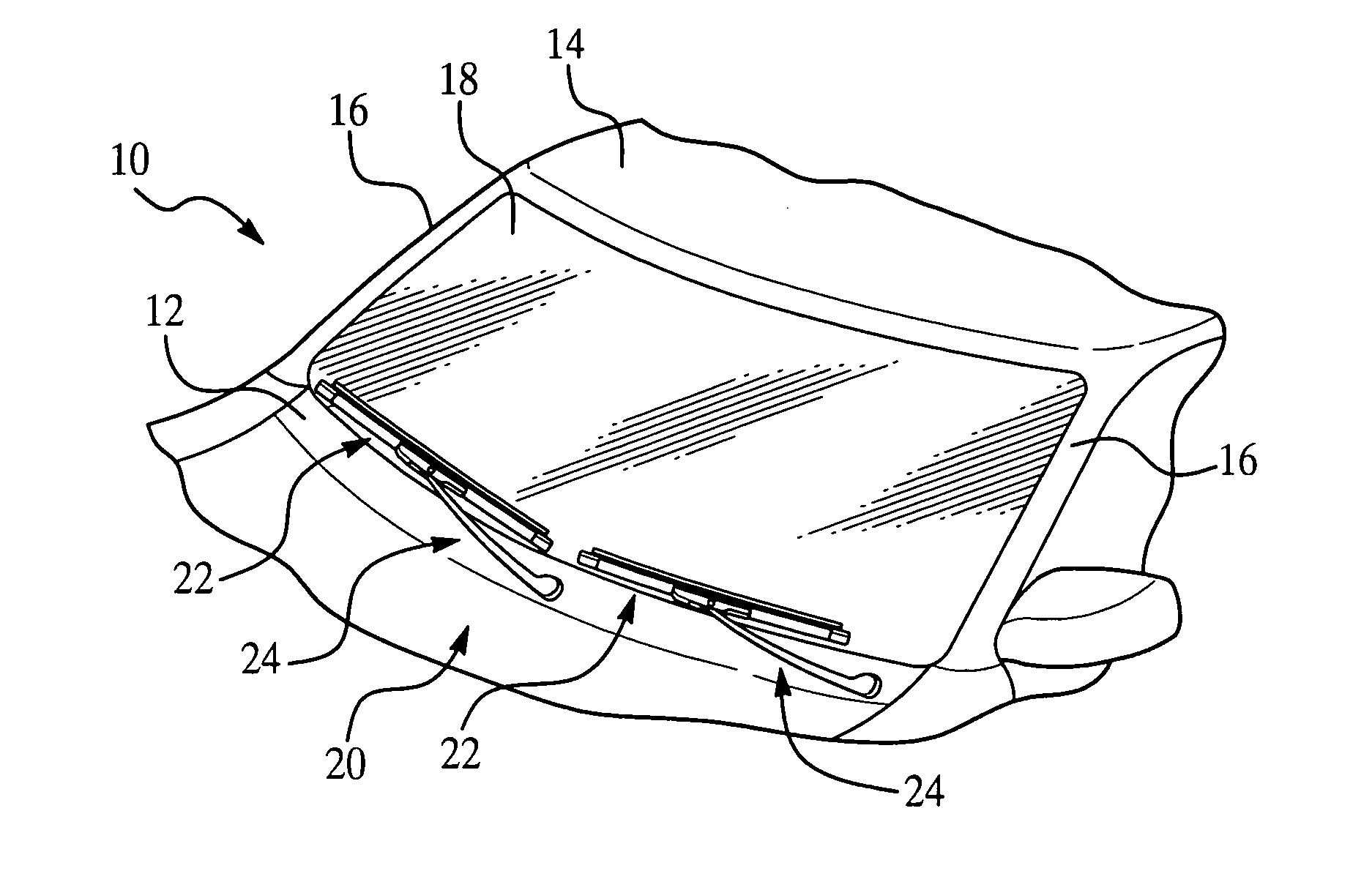
[0022]Referring now to the figures, where like numerals are used to designate like structure, a portion of a vehicle is illustrated at 10 in FIG. 1. The vehicle body includes a cowl 12, a roof 14, and a pair of laterally spaced front or “A” pillars 16 extending between the roof 14 and the cowl 12. The A-pillars 16, roof 14, and cowl 12 cooperate to define a generally rectangular perimeter, which supports a curved or “swept back” windshield 18.

[0023]A windshield wiper system is generally indicated at 20 in FIG. 1 and is employed to clean the glass windshield 18. The windshield wiper system 20 includes a pair of beam blade windshield wiper assemblies of the present invention, generally indicated at 22, and which correspond to the driver and passenger side of the vehicle 10. Each beam blade windshield wiper assembly 22 (hereinafter “wiper assembly”) is carried by a corresponding wiper arm assembly, generally indicated at 24. The wiper arm assembly 24 includes an attachment member (not...


PUM


Abstract

A beam blade wiper assembly including a rubber wiping element and an elongated beam having first and second longitudinal ends. The wiper assembly also includes an airfoil having an attachment portion and an upper portion extending between first and second distal ends. The attachment portion includes a flat rib and a pair of legs adapted to operatively engage the rubber wiping element. The upper portion includes a solid base having a leading edge that extends from the base toward the wiping element. The base and the rib define a space that receives the elongated beam. The base and the elongated beam define a cavity that provides flexibility between the upper portion and the attachment portion during wiper operation. The upper portion further includes a spoiler that extends from the base in a manner opposite to the leading edge.

Description

CROSS-REFERENCE TO RELATED APPLICATION(S)[0001]This application is a divisional of U.S. Ser. No. 11 / 345,930 entitled “Beam Blade Windshield Wiper Assembly Having an Airfoil” and filed on Feb. 2, 2006.BACKGROUND OF THE INVENTION[0002]1. Field of the Invention[0003]The present invention relates, generally, to windshield wiper assemblies and, more specifically, to a beam blade windshield wiper assembly having improved wind lift characteristics.[0004]2. Description of the Related Art[0005]Conventional windshield wiper assemblies known in the related art generally consist of two types commonly referred to as “beam blade windshield wiper assemblies” and “tournament windshield wiper assemblies.” Both types of windshield wiper assemblies include a wiping element that contacts the windshield or surface to be wiped. Further, both types of windshield wiper assemblies are carried across the windshield by a wiper arm and rely on the downward force from the wiper arm to maintain contact between t...

Claims


Application Information

Patent Timeline
Patent Type & Authority Applications(United States)
IPC IPC(8): B60S1/32
CPCB60S1/38B60S1/381B60S2001/3818B60S1/3891B60S1/3881
Inventor MOLL, KYLELOZANO, ROLANDO
Owner TRICO PROD CORP
Why Eureka
Eureka Blog
Learn More