Torsional support apparatus and method for craniocaudal rotation of animals

a torsional support and animal technology, applied in the field of imaging systems, can solve the problems of lack of means, and none of them provide all of the advantages of direct immobilization of recumbent animals

Inactive Publication Date: 2010-01-28
BRUKER BIOSPIN
View PDF90 Cites 34 Cited by
  • Summary
  • Abstract
  • Description
  • Claims
  • Application Information

AI Technical Summary

Benefits of technology

[0023]The present invention not only provides all of the advantages previously described for directly immobilizing the animal in a recumbent posture on an optically transparent planar su

Problems solved by technology

Second, the human experimenter has access to the animal.
On the other hand, direct immobilization of a recumbent animal onto a planar support is disadvantageous in that in known imaging systems a means is lacking to precisely control the craniocaudal rotation angle, and hence the view angle, of the animal, for example to ±5 degree precision.
This difference may result in artifacts, such as relative attenuation or enhancement of a molecular signal, upon comparison to the first-time set of multimodal molecular images.
Similarly, this difference may lead to a result that the first-time set of images and the at least second-time set of images will not be co-registered, thereby degrading the quantitation provided by a simple regions-of-interest analysis wherein a single regions-of-interest template is applied to both the first-time set of images and the at least second-time set of images.
Although imaging systems are known that can obtain multiple views of an animal with a stationary camera system wherein the view angle is more precisely controlled,

Method used


Image

  • Torsional support apparatus and method for craniocaudal rotation of animals
  • Torsional support apparatus and method for craniocaudal rotation of animals
  • Torsional support apparatus and method for craniocaudal rotation of animals

Examples


Embodiment Construction

[0068]The invention now will be described in detail with particular reference to certain preferred embodiments thereof, but it will be understood that variations and modifications can be effected within the spirit and scope of the invention. The following is a detailed description of the preferred embodiments of the invention, reference being made to the drawings in which the same reference numerals identify the same elements of structure in each of the several figures.

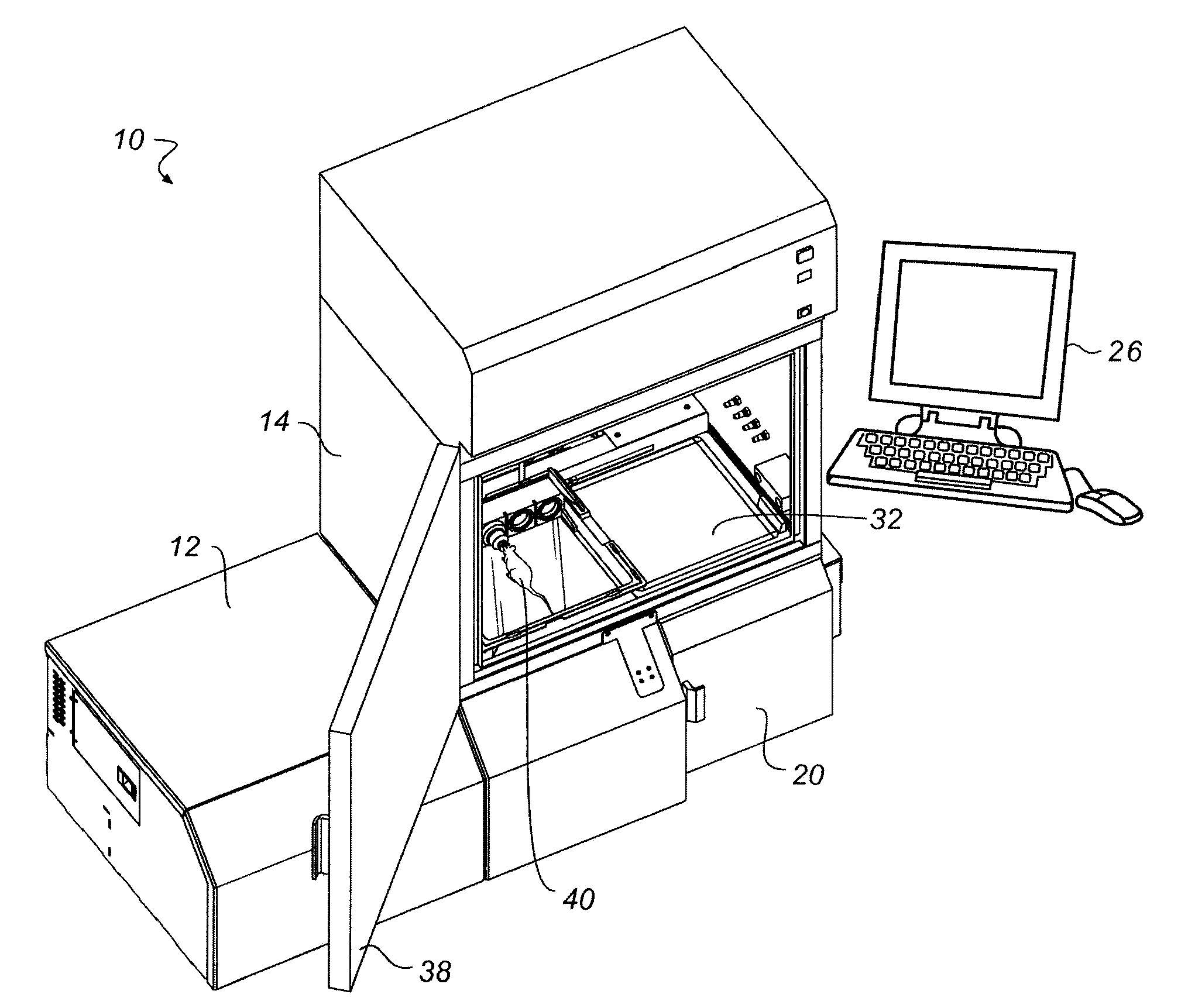
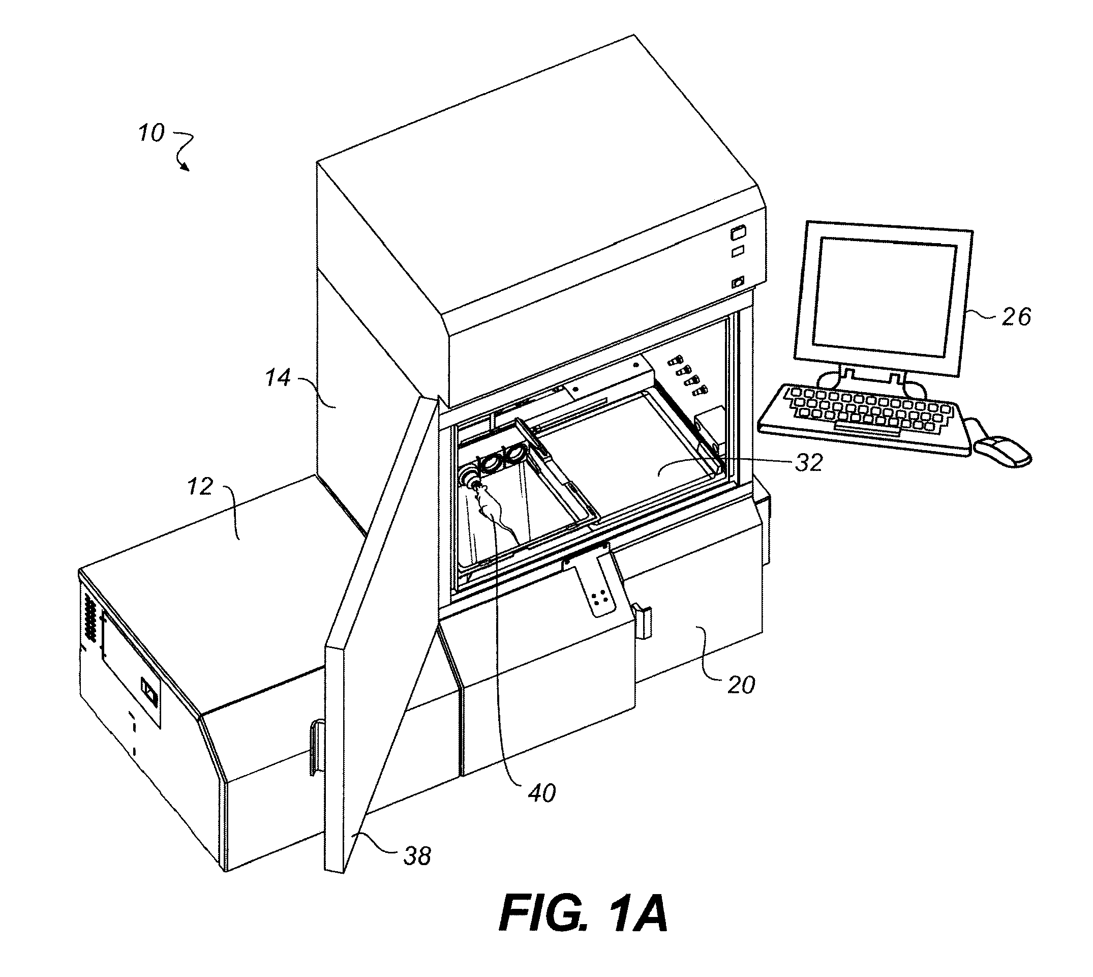
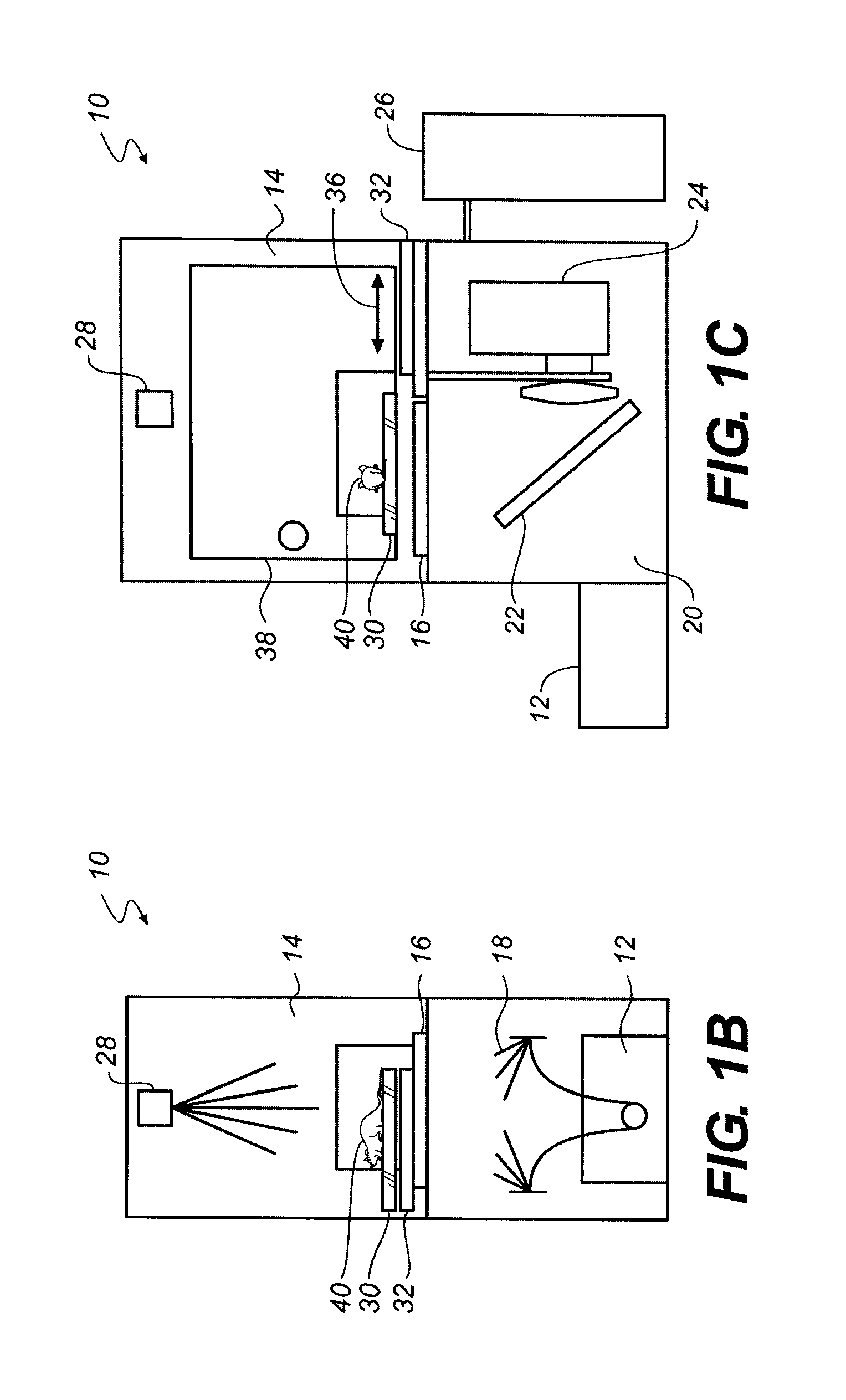
[0069]FIGS. 2A and 2B show electronic imaging system 10, including a removable high-resolution phosphor screen 32, such as described in the previously mentioned application of Vizard et al, but configured in accordance with the present invention with a torsional support apparatus 300 inside sample environment 14. Alternatively, a high-sensitivity phosphor screen or a multiple panel phosphor screen may be used such as described in the previously mentioned application of Feke et al. Those skilled in the art will appreci...


PUM


Abstract

A torsional support apparatus is disclosed for craniocaudal rotation of test animals to enable multiple-view imaging. The animal is supported in a U-shaped loop of optically transparent material and the loop is moved to apply torsion to the animal to rotate it about its craniocaudal axis. Methods of imaging also are disclosed that use the torsional support technique.

Description

CROSS REFERENCE TO RELATED APPLICATIONS[0001]Reference is made to and priority is claimed from provisional U.S. Patent Application Ser. No. 61 / 131,948, filed Jun. 13, 2008 by Feke et al entitled TORSIONAL SUPPORT APPARATUS FOR CRANIOCAUDAL ROTATION OF ANIMALS, the disclosure of which is incorporated by reference into this specification.[0002]This application is a Continuation-In-Part of the following commonly assigned, copending U.S. Patent Applications, the disclosure of each of which also is incorporated by reference into this specification:[0003]U.S. Ser. No. 11 / 221,530 filed Sep. 9, 2005 by Vizard et al., entitled APPARATUS AND METHOD FOR MULTI-MODAL IMAGING;[0004]U.S. Ser. No. 12 / 196,300 filed Aug. 22, 2008 by Harder et al., entitled APPARATUS AND METHOD FOR MULTI-MODAL IMAGING USING NANOPARTICLE MULTI-MODAL IMAGING PROBES;[0005]U.S. Ser. No. 12 / 354,830 filed Jan. 16, 2009 by Feke et al., entitled APPARATUS AND METHOD FOR MULTI-MODAL IMAGING;[0006]U.S. Ser. No. 12 / 381,599 filed...

Claims


Application Information

Patent Timeline
IPC IPC(8): A61B5/05
CPCA61B5/0059A61B6/00A61B2503/40A61B6/4417A61B6/04A61B5/0082A61B5/6887A61B6/508A61D7/04A61M5/007
Inventor FEKE, GILBERTGELDHOF, BENJAMIN F.LEEVY, WARREN M.BRIDGES, MARK E.MCLAUGHLIN, WILLIAM E.PAPINENI, RAO
Owner BRUKER BIOSPIN
Why Eureka
Try Eureka