Method and system of imaging electrons in the near earth space environment

a near earth space environment and electron imaging technology, applied in wave based measurement systems, instruments, reradiation, etc., can solve the problems of radiative light emission levels, electron density is not high, and affect the entire near earth space environmen

Inactive Publication Date: 2010-01-21
GOVT OF USA REPRESENTED BY SEC OF THE NAVY CHIEF NAVAL RES ONR NRL CODE OOCCIP
View PDF4 Cites 15 Cited by
  • Summary
  • Abstract
  • Description
  • Claims
  • Application Information

AI Technical Summary

Problems solved by technology

These disturbances propagate through interplanetary space in the solar wind and impinge upon the Earth's magnetic field thereby affecting the entire near Earth space environment.
(1) A first physical mechanism considered was the outermost edge of the plasma regions where the brightness of 30.4 nm helium emissions drops off (i.e., where He+ represents the outermost edge). This edge region is called the plasmapause. The quantities imaged were not electrons, but rather helium ions in the plasmasphere. Models tacitly assumed a fixed relationship to the electron distributions. Thus, what was considered was a poor proxy for determining the electron density. This emission was discovered by a U.S. Naval Research Laboratory (NRL) rocket experiment in 1969, and had been routinely imaged extensively by the EUV experiment conducted on the National Aeronautics and Space Administration (NASA) Imager for Magnetopause to Aurora Global Exploration (IMAGE) satellite. FIG. 1 shows a typical image from the IMAGE satellite. The principal drawback of this technique is that the electron density is not measured directly; and He+, which is the proxy for electron density, is typically of the order of 10 percent of the electron density in the plasmasphere, but can be as much as fifty percent or as low as one percent, approximately.
(2) A second physical mechanism considered was radiative recombination of the H+ plus an electron (i.e., H++e) into the ground state of Hydrogen (H), resulting in a narrow continuum emission at 91.1 nm. The intensity is the integral along the line of sight of the product of the recombination rate times the electron density and the proton density; the integrand is essentially the square of the electron density. In the ionosphere, the intensity level when viewing in the vertical is of the order of a few Rayleighs, but the recombination there is with oxygen (O) ions (the continua are close in wavelength due to the nearly identical ionization potentials of H and O). The Rayleigh is a unit of measure of the perceived power of light (i.e., luminous flux) used to measure the weak emission of light (i.e., air glow), such as of an aurora). The drawback with this approach is that in the plasmasphere, estimated radiative light emission levels are of the order of millirayleighs, which would challenge detection by current EUV technology. In addition, in the magnetosphere, the signal is much lower.
Thus, the NASA IMAGE satellite, which was operational from 2000 to 2005 provided some limited imaging capability, measuring helium ions in the plasmasphere and energetic neutral atoms from the inner magnetosphere, instead of measuring electrons directly.
However, the differences presented herein involve Geocorona instruments specifically designed and tailored for the application of geospace imaging.
Thus, there are no known methods and / or systems for directly imaging electrons in the near Earth environment and to study the global shape of the magnetosphere profile.

Method used


Image

  • Method and system of imaging electrons in the near earth space environment
  • Method and system of imaging electrons in the near earth space environment
  • Method and system of imaging electrons in the near earth space environment

Examples


Embodiment Construction

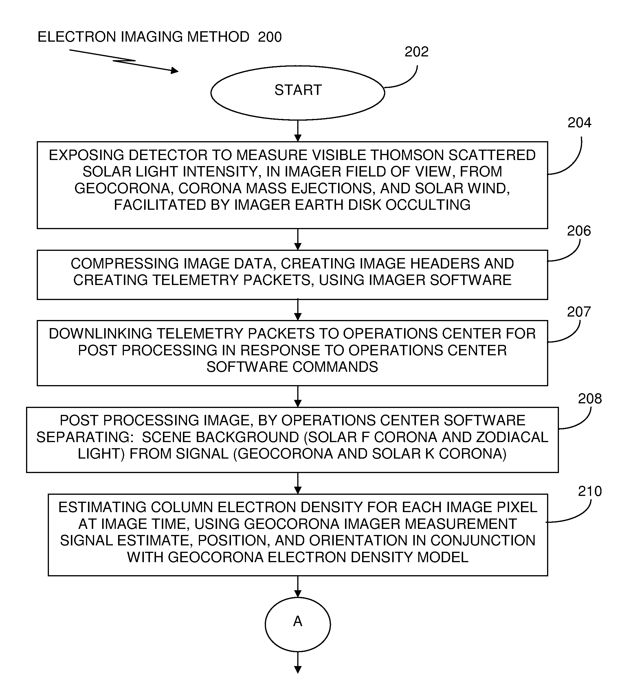
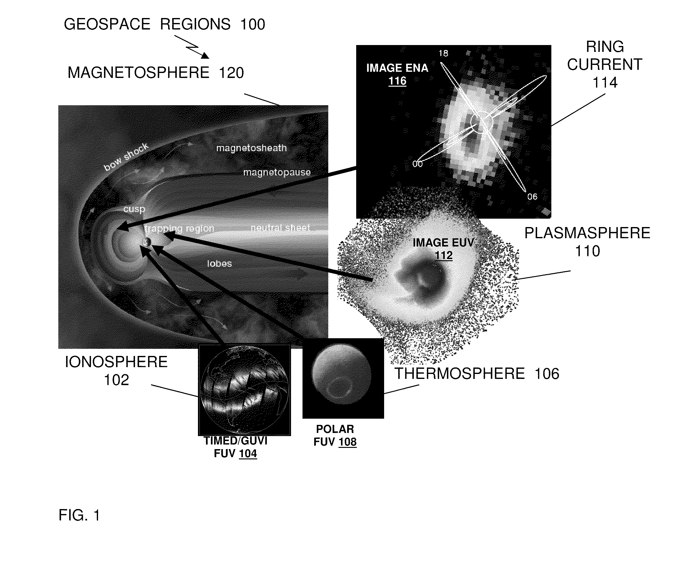
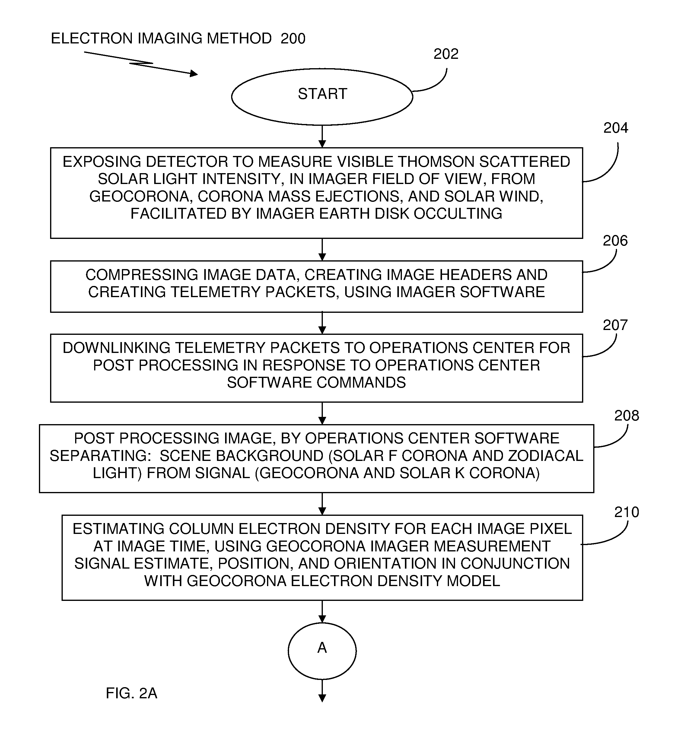
[0044]Preferred exemplary embodiments of the present disclosure are now described with reference to the figures, in which like reference numerals are generally used to indicate identical or functionally similar elements. While specific details of the preferred exemplary embodiments are discussed, it should be understood that this is done for illustrative purposes only. A person skilled in the relevant art will recognize that other configurations and arrangements can be used without departing from the spirit and scope of the preferred exemplary embodiments. It will also be apparent to a person skilled in the relevant art that this invention can also be employed in other applications. Devices and components, described in the exemplary embodiments can be off the shelf commercially available devices or specially made devices. Further, the terms “a”, “an”, “first”, “second”, and “third” etc. used herein do not denote limitations of quantity, but rather denote the presence of one or more ...


PUM


Abstract

A method and system of globally monitoring space weather conditions, use an imager, including one or more telescopic instruments and one or more processors, containing computer program code. The imager is configured on a platform; and positioned in the near Earth space environment, where, based on the executed computer program code, the imager compiles information about space weather conditions, by directly detecting electron emissions on a global basis. Network interfaces coupled with the imager provide, over a communications network, a plurality of communications and information, about space weather conditions, between the imager and a plurality of operational space assets and operational Earth assets. The plurality of communications and information about space weather conditions includes signals and information which automatically alert the plurality of operational space assets and operational Earth assets of effects of a solar wind.

Description

RELATED APPLICATIONS[0001]The present application is related to and claims the benefit of priority under 35 USC § 119(e) of prior filed provisional U.S. patent applications 61 / 081,827 and 61 / 081,855 which are each herein incorporated by reference in their entirety.FIELD OF THE INVENTION[0002]The present invention relates to observing and imaging the outer terrestrial atmosphere. More particularly, the present invention uses scattering of solar visible light by electrons in a near Earth space environment, including the plasma region and offers a means of imaging the electrons directly, on a global scale, in order to image the solar wind and coronal mass ejection interaction with the Earth. Thus, the detection of electrons by measuring the solar light scattered by the electrons will provide the ability to directly observe national and international space weather conditions.BACKGROUND OF THE INVENTION[0003]The near Earth space environment, also known as a geospace environment, or “geos...

Claims


Application Information

Patent Timeline
Patent Type & Authority Applications(United States)
IPC IPC(8): G01W1/00
CPCG01W1/00
Inventor MEIER, ROBERT R.SOCKER, DENNIS G.CARTER, MICHAEL TIMOTHYCHUA, DAMIEN HANENGLERT, CHRISTOPH R.HUBA, JOSEPH DONALDKORENDYKE, CLARENCE M.KRALL, JONATHAN FRANCISPICONE, JULIAN MICHAELSLINKER, STEVEN PAULVINCENT, WILLIAM SULLIVAN
Owner GOVT OF USA REPRESENTED BY SEC OF THE NAVY CHIEF NAVAL RES ONR NRL CODE OOCCIP
Why Eureka
Try Eureka